-> Want to skip ahead? Here’s the next installment.
In the previous installment, we introduced the case study requirements. Today our goal is to analyze them a bit and then begin organizing the entire system into special packages called ‘domains’. This is a term that is sometimes defined rather loosely. We crank the definition down a bit tighter in Executable UML to suit our modeling and code generation goals, as you’ll see in today’s installment.
Some light requirements analysis
If you haven’t read through the Elevator System requirements yet, it’s a good idea to take a look before proceeding.
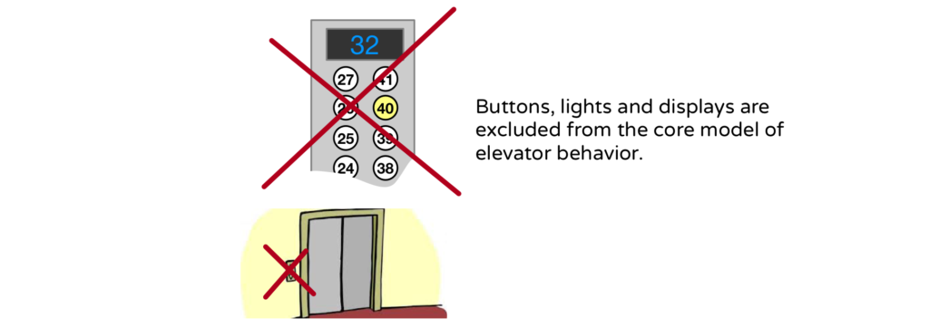
Pushing buttons A quick scan through the requirements reveals many assumptions about passengers pushing buttons. Are buttons such a foundational necessity? Could we consider alternate communication methods such as voice or gestures? (There are times when I’ve felt the need to gesture at my apartment building’s elevator ;). While the user interface will be important in our system, it is not essential to defining elevator behavior. We can, for example, abstract a button push as a Stop request(atShaft, toFloor) command without regard for the specific mechanism which issues it. Consequently, we can keep the UI technology separate from the core model of elevator behavior. That said, it is often helpful to describe use cases in terms of buttons, but when I do that, I really mean the command issued by the button. I point all this out since, historically, many treatments of the elevator example pointlessly revolve around button logic.
Moving the cabin We need to provide variable cabin speed staying within a specified G force tolerance. This means we must do some math and physics to control the motors.
Delivery algorithm? There is no specified algorithm for delivering cabins. This is an obvious hole in the requirements. The requirements do state that passengers should wait as little as possible. Obviously. But we aren’t given a specific time limit. It looks like this one is up to us. We’ll need to choose or devise some algorithm.
Varying service We need to provide express service by skipping floors for certain cabins. But we’ll need to think carefully about how this works. For example, when you push the up button at some floor it does you no good to have a cabin arrive that can’t stop at the desired destination.
And so on…
On a real project, before doing any modeling, you should certainly try to fill in as many gaps as possible before proceeding. This involves interviewing subject matter experts, reading background documents, taking notes, drawing informal illustrations and presenting them for feedback, examining existing elevator systems, googling, etc. These are all subjects for another series of articles or perhaps even a book. Here, we’re focusing on the modeling task, so let’s just assume that all the experts are on vacation and we are left on our own so that we can get on with the modeling.
While the initial requirements analysis may be complete, you can be sure that as you model you will often find yourself in a position to question the source requirements. That’s a key purpose of the modeling process. It exposes holes and imposes clarity upon the original requirements. So, we are certainly not finished with requirements analysis. We are merely done reading through the written requirements.
Step 2: Create a Domain Diagram
In the previous article in this series I listed the steps we follow on an xUML project. Now here we are at Step 2.
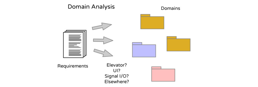
We want to construct a complete picture of the elevator system in terms of modeled and non-modeled components along with their interdependencies. We do this by constructing a domain diagram to account for every software detail necessary to define a fully executable system. In Executable UML, there is no magical aether to which “implementation details” are deferred. The phrase “implementation details” all too often is code for “stuff to hard to think about at the moment”.
In Executable UML, there is no magical aether to which “implementation details” are deferred Click To TweetBy accounting for everything up front, we gain the freedom to exclude certain details from one model knowing that those details will be handled in a some designated domain.
Analysis Paralysis? Domains to the rescue
In UML notation, domains are represented as folder packages or block-style as SysML components. Either way, these are not just arbitrary collections of model elements. Domains represent semantic boundaries and, organized properly, are key to avoiding analysis paralysis. A little history may be helpful in understanding the problem that domains are intended to solve.
In my early days of class modeling I would often make rapid initial progress and then stall out on about the 10th or 15th class. And it wasn’t just me. Numerous projects reported a problem called “analysis paralysis” in which the modeling effort would stall out, mired in uncertainty. This paralysis was often resolved by abandoning the task and writing code.
My mentor at the time, Sally Shlaer, correctly recognized the invisible wall as a thing she called a “semantic gap”. In the context of the elevator model, it might play out like this:
Hmm, an elevator system consists of some number of Shafts. Each Shaft has a Cabin riding up and down inside it. Each Cabin has a Door that opens and closes. So far so good, the class model is practically building itself! Okay, so a Door has a Motor that opens and closes it, hmm, or does it have two? And there must be a Sensor that detects the closing of the Door. Is it a contact sensor or infrared? Actually, I need a Sensor that detects when the Cabin crosses a floor boundary. How do I model a relationship to Sensors? Do I superclass everything that could possibly have a sensor (or three)? What about a class related to multiple sensors? I’m going to have a graphical user interface so that the administrator can lock out certain floors. Do I model a relationship between floors and some kind of boundary icon? Actually, most physical elements will be represented by some kind of icon. Must I now superclass all entities with a graphical representation? And so forth…
The semantic shift occurs when you leap from one tightly related set of terminology to a completely different terminology. Like trying to mix the Star Trek and Star Wars universes, nothing good can come of it. Each universe has its own internally consistent rules and terminology. For example, it’s easy to model concrete relationships among Door, Cabin, Shaft and Floor. Every Door opens into exactly one Cabin. A Floor physically intersects at least one Shaft, etc. Here we have a cohesive vocabulary. But now let’s bring in our graphical administrative UX. You can imagine that some or all of the physical instances might map to some kind of visual representation such as an Icon or some kind of graphical entity. But how do you model that? You could try generalization and superclass the whole mess into something like “Physical Entity is represented by exactly one Icon”. Or many? Or is it represented by a row in a table? Wouldn’t you want the flexibility to reconfigure the UX without having to redo all your models? You’ll run into the same problem when you start thinking about sensor/actuator configurations. When you make this jump from an elevator thing to a general purpose thing you end up with rather complex relationships that are difficult to resolve in a class model. The solution is to model all of these vocabularies separately, each in their own black box.
This leads us to the xUML definition of a domain:
A distinct physical or abstract subject matter with its own internally consistent vocabulary, rules, policies and behaviors.
This definition is rather abstract itself and will make more sense in terms of a few counterexamples.
Notice that there is nothing in the domain definition about hardware or software units of organization. This means that a single domain could be implemented using one or many cpus, tasks, cloud services, threads, libraries, or any packaging. In fact, multiple domains could all be packed into a single executing loop as is the case with the code generation scheme described used in our book, Models to Code. So the boundary of a domain is entirely platform independent.
A domain is not a political boundary. So we don’t define a domain as “what department X is working on”. Domains are also organization-independent. In other words, you can deploy the work onto a variety of organizational units.
The oh so tangible nature of hardware, software design and political boundaries is difficult to ignore on real projects. It requires a bit of mental rewiring and a lot of modeling experience to see past platform specific artifacts and learn to organize a system around platform independent subject matter boundaries instead.
We don’t need the following domain in our elevator system, but I hope it can illustrate domain thinking.
Consider a linear algebra math library. No, wait, forget about the library part and just think about the subject matter. There is a distinct vocabulary consisting of matrices, vectors, eigenvalues and such. There are rules for operating on these elements. This fits our domain definition nicely. You can describe the rules and concepts of linear algebra without specifying any particular implementation packaging.
A domain is not a high level function. We name the domain “Linear Algebra” without regard to any particular function. If, instead, we named the domain Matrix Multiplier, we end up with a subset of the things you can do with matrices. Later, if we create a separate domain called “Linear Equation Solver”, we would need to duplicate many of the same model elements to get it to work. You might think this would never happen, but, believe me, it does. That’s because one person, often a system engineer SysML’ng around makes the split which eventually makes its way down to two separate software engineering teams. These two teams then replicate components without, especially in a large organization, necessarily being aware of each other.
Domains partition a system by vocabulary rather than function. It follows, then, that the same class, with the same name and definition, should not appear in more than one domain on a given project.
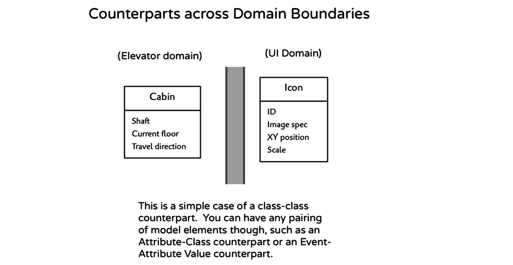
Domains partition a system by vocabulary rather than function. Domains are not confined to political boundaries. Click To TweetFor example, if the Cabin class is defined in an Elevator Management domain, it shouldn’t make an appearance in any other domain. But the Cabin class may be mapped to one or more counterpart model elements (not necessarily classes). Going back to the Linear Algebra example, a View class in a graphics domain might have a counterpart Matrix in the Linear Algebra domain. Or, in our Elevator example, a Cabin class might have a counterpart Icon in a User Interface domain. Both the Cabin and Door classes may have counterpart Signal Groups in the Signal IO domain.
Back to work: Define the Application Domain
Enough theory and definitions for now, let’s get on with the work. We start by identifying the subject matter most important to our Elevator System, the application domain.
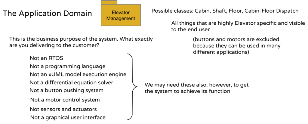
The application represents the pure business purpose of the system without regard to any particular enabling services. Judging from our requirements, we can see that this purpose is to provide the ability to deliver cabins to the expected floors, operate them safely and provide for re-configurable service.
To support this capability, we will probably think in terms of coordinating physical entities such as Cabin and Doors and specifying delivery in terms of Shaft and Floor. We also may need some non-physical organizational entities to group Floors or Shafts for express delivery. The basic theme here, though, is Elevator Management, so that is a suitable name of our application domain.
All the other stuff we may need (motors, actuators, sensors, model execution, buttons, GUI) is subservient to the needs of our application and will be delegated to other domains.
Furthermore, classes within the Elevator Management domain will be highly elevator specific. This frees up all of the other domains we need to be more general purpose (button, for example) that can be configured for elevator specific use, but could, potentially be reused in entirely different applications.
In the next installment we will sketch out these other non-elevator domains and see how they all fit together to define a complete system. Then we will dive into the Elevator Management domain and begin modeling it in painstaking detail.
I help agile software teams succeed with requirements analysis, domain definition, platform independent, executable modeling and high quality code generation. Other websites: executableuml.org, modelstocode.com





Where would something like access policies fit? For example, some floors might require rider authentication and authorization in order to qualify as a target destination. Just throwing in another aspect. Perhaps this is concern becomes another type of constraint similar to express travel. This sort of thinking tends to put me into the dreaded analysis paralysis mode.
Hi Dan, great question! So I imagine a passenger with a magnetic card unlocking access to their own floor at a hotel along with certain public floors like the restaurant and mezzanine. Or maybe hotel personnel with a card that permits all access. That sort of thing
Core signals modeled in the application domain such as Goto floor( Shaft, Floor ) shouldn’t be altered, since that would unnecessarily complicate elevator dispatch. Keep the core simple. But some kind of screening could be applied before the signal is generated. If a user doesn’t have access, they can’t issue a given signal with certain parameter value ranges.
Push the screening to a UI domain? No. Two problems with that. For one, if you have an alternate interface, as many physical systems do, such as a network or command line interface, you end up with an unsecured command source. Hard to imagine in an elevator scenario, but not inconceivable. Presumably, you want the same screening applied regardless of command source. This suggests a dedicated access domain that is used regardless of command source. But the real issue is that the subject matter of security and access is distinct. It has little to do with the semantics of a UI. And, having modeled this in the past, I’ve got the classes to prove it!
So that’s my answer. Model access level security separately in its own domain since, modeled correctly, it has nothing to do with elevators or UIs. (But can be configured to work with both).
Thanks, Leon. Adding the access control domain allows us to maintain focus on the elevator subject. I’m looking forward to a seeing how we’ll bridge the elevator domain to the access control domain when the time comes. Even if we have to make changes ot the elevator domain to accomplish the bridging, I bet it will be less effort to do so than if we were expressing the rules in C or C++…
Nice quote:
“The phrase ‘implementation details’ all too often is code for
‘stuff to hard to think about at the moment'”
Thanks, Andreas!