-> Want to skip ahead? Here’s the the next installment.
Having nailed down the Elevator Management application domain in the previous installment, we ask, what capabilities and details remain to be addressed? There are quite a few!
Contents
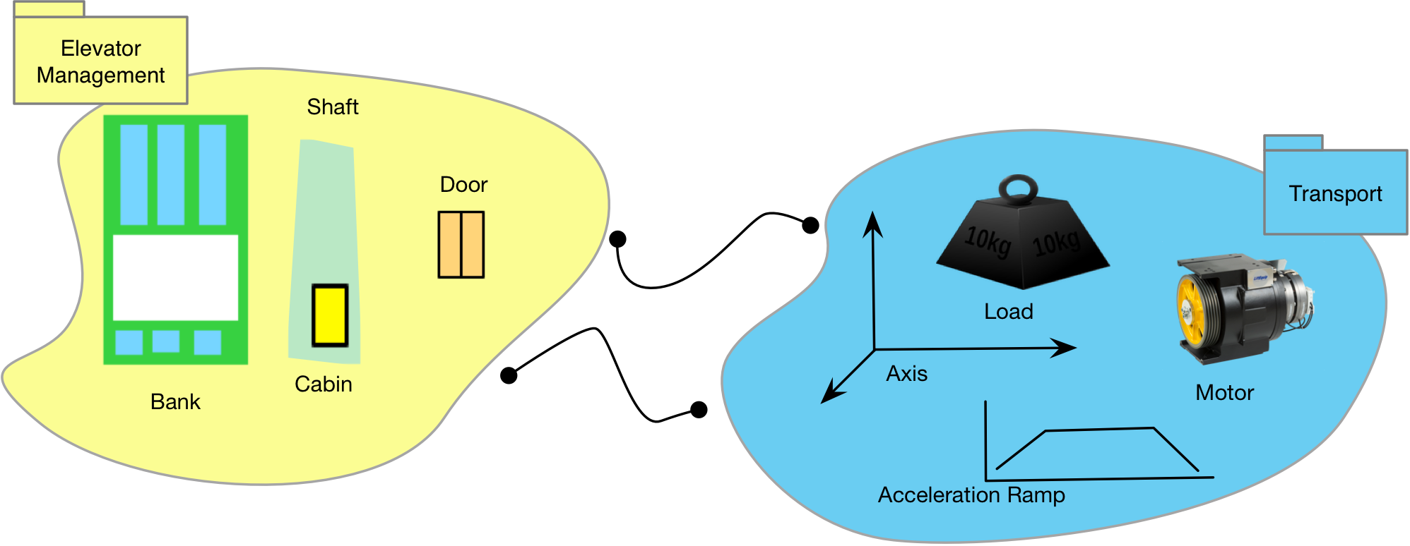
For example, our application domain’s model of elevator behavior excludes any means of communicating with either passengers or administrative users (see requirements). So we can assume that there might be at least one domain that deals with the language of UI elements. Let’s call it the UI domain for now.
We also have no way of communicating with physical devices such as motors and position sensors. So we need at least one domain to coordinate with all of that. Let’s call it Signal I/O for now.
Our initial domain diagram looks like this:
Service Domains
The two domains at the bottom each provide a service to the Elevator Management domain. By service, we mean that a domain is providing capabilities required so that some other domain can accomplish its task. We use the service-client terminology to express this concept. In our initial domain diagram, the UI is a service domain and the Elevator Management domain is its client. Can a service support multiple clients? Yes, as we will soon see.
When we propose the existence of some domain, we should be able to guess a few key classes that might be modeled inside it. If you can’t, it’s a bad sign. Remember the xUML domain definition from the previous installment. We partition the system by its data, not its functions. I’m going to repeat that. Domains are partitioned by data, not function.
When you look inside a domain you should find a closely related collection of classes and relationships at the same level of semantics. Click To TweetA principle of exclusion is equally important. You should have a clear rule about what classes will NOT be in your domain. This is key to successful modeling and the avoidance of analysis paralysis. If you don’t know what to exclude (and why) from your model, you will never know when you are finished!
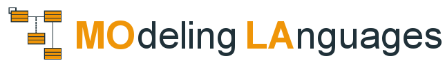
We did this exercise for the Elevator Management domain in the previous installment and determined that we should include elevator specific classes such as Door, Cabin, Shaft, etc. Anything with a general purpose flavor (like Icon, Bit Field or Sensor) should be excluded. Now let’s apply the same inclusion/exclusion process to our two proposed service domains.
UI
For the passenger UI, we need to deal with elements like lights and buttons on physical panels. The administrative interface will use more abstract widgets such as icons and tables. Should physical buttons and lights be in the same domain as icons and other graphical entities? Yes, and no. From a software perspective, the physical aspect of a button is simply that you need to translate an analog signal or digital command into a button state. But the button state, pushed, held, etc. is pretty much the same as that of a button widget. After all, GUI buttons were originally conceived as a simulation of the real thing. So, yes all buttons, lights and controls, physical or otherwise are part of the UI. We just need some way to detect and generate electrical signals and map those to corresponding UI features.
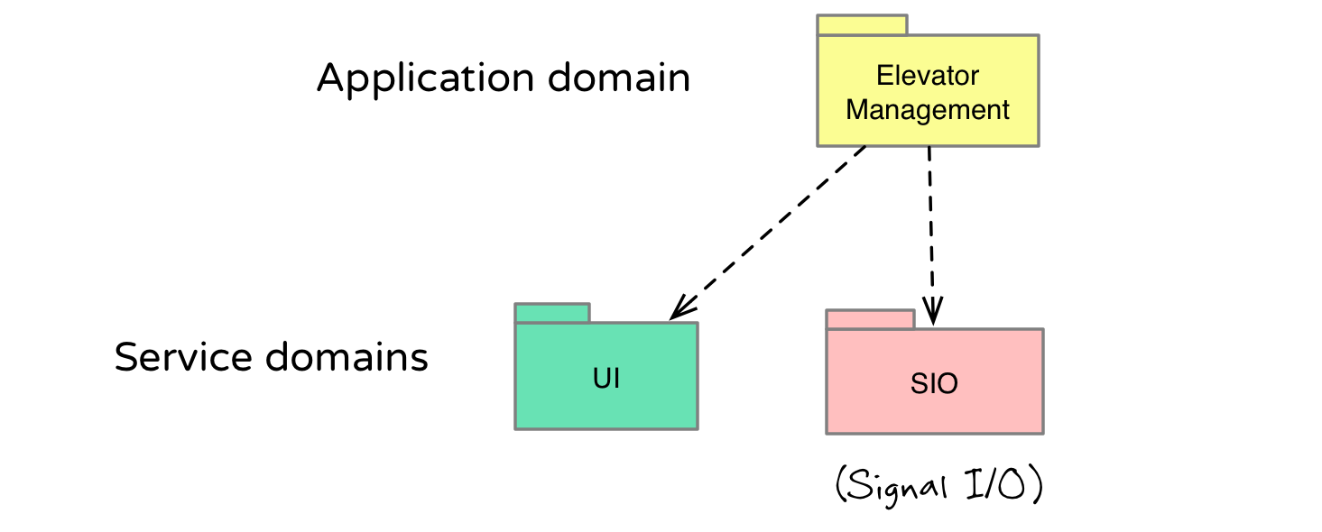
The UI should know nothing about the internals of its application. We won’t find any elevator specific classes such as Cabin in the UI domain, for example. But there may be an Icon class that can be configured to represent a real world cabin. Typical UI classes for controlling the elevator might be Button, Panel, Light. For the administrative interface, we probably have Table, Row, Icon, Zone, and any other element useful for visualizing our data.
Signal I/O
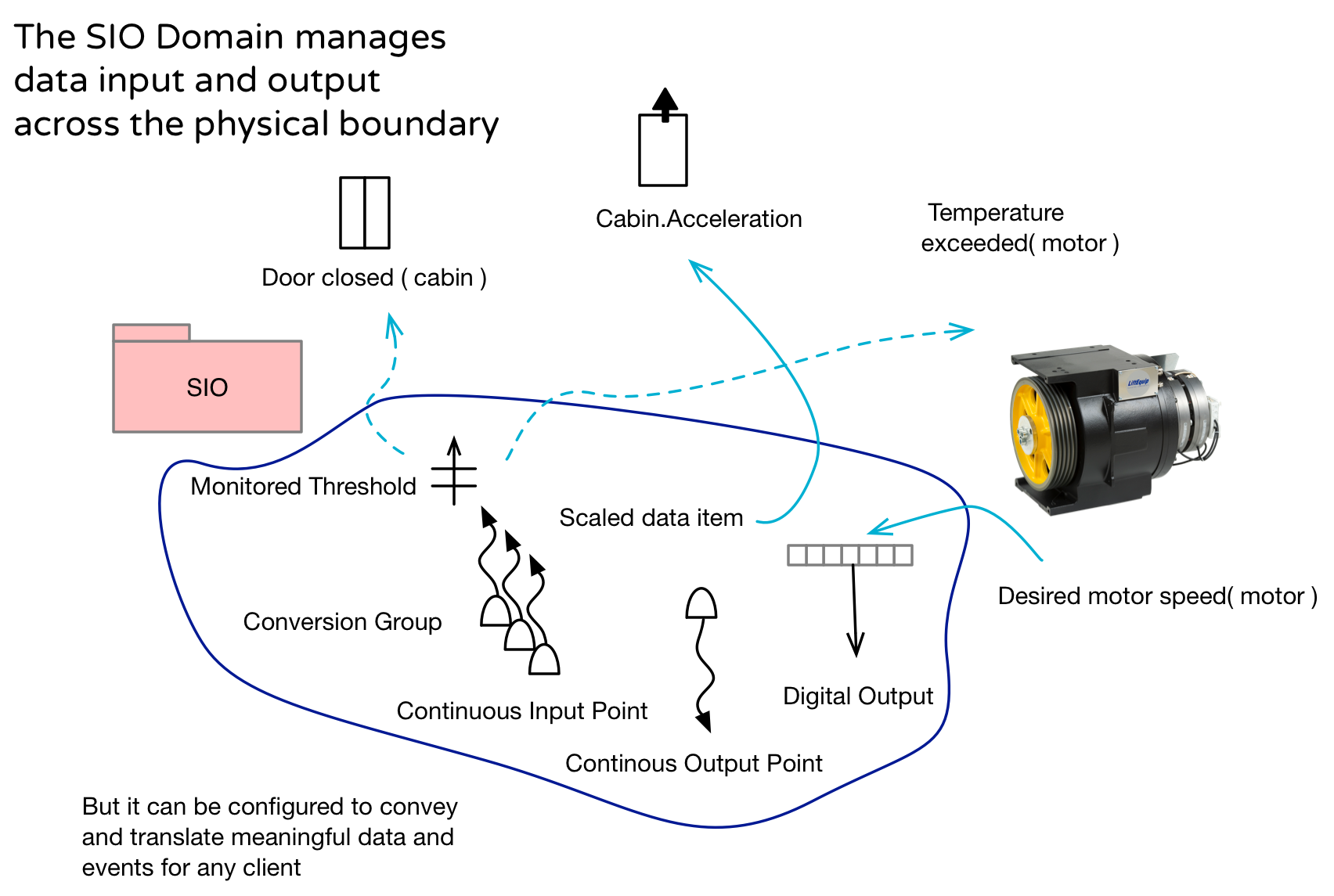
Signal I/O, or SIO as we usually write it, is a common domain in physical systems. It manages input and output signals between the physical electronics and any domain that requires sensor based attributes or issues signals that should result in real world physical activity, usually via an actuator of some sort. For example, the Elevator Management domain will want to issue a signal output that sets a motor speed or opens and closes a door. It will also want to know the current speed and direction of each cabin.
One particularly helpful feature of SIO is that it takes over all periodic signal monitoring so that all other domains can be event driven. One group of signal inputs might be monitored every 50 ms while another set is sampled every 100 ms. The incoming data is then conditioned, transformed and possibly checked against range limits. The client domain can then have a sensor based attribute updated or just get an event when a certain threshold is crossed. This greatly simplifies the client domain models since they now don’t need to loop around in every state checking sensor values.
SIO knows all about signals but has no idea what the data in those signals mean. The fact that a value is “RPMs”, for example, has no significance in SIO. Possible classes such as Input Point, Threshold, Range Limit, Sample Group, Scale Specification and so forth reinforce this principle.
We devote a whole chapter to this domain in our book Models to Code.
Dependency between domains, aka Bridge
When defining dependencies between domains we aren’t thinking about the flow of data or control (the domain initiating any given interaction). Instead, we ask which domain requires the other. So you can interpret the arrows as the ‘flow’ of requirements. In Executable UML, the dependency represented by each arrow is called a “bridge”.
SIO, for example, is a general purpose domain that could support a variety of clients communicating with the outside world. So, SIO doesn’t need the Elevator Management application to perform its function, though it does assume that some client domain will use SIO’s capabilities. The Elevator Management domain, however, needs SIO, otherwise our application wouldn’t be able to interact with the physical world. So we can say that the Elevator Management domain requires the capabilities of the SIO domain.
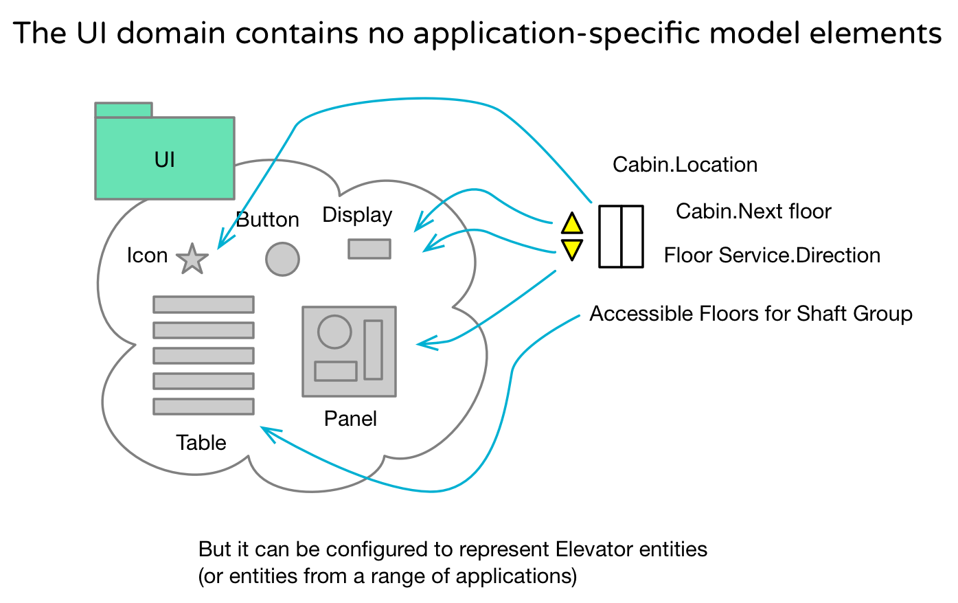
In fact, if we are using SIO to supply physical button push signals as well as turning on arrow lights, there is surely a dependency between the UI and SIO. UI needs SIO to update physical displays and detect physical button presses, so let’s update our domain diagram accordingly.
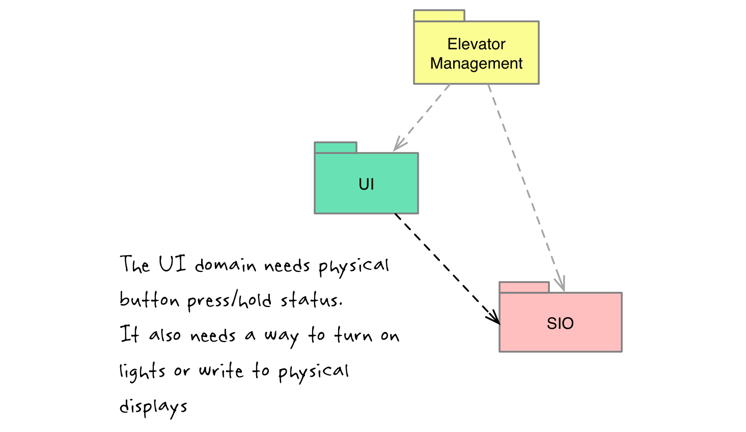
The bridge (arrow) between Elevator Management and the UI domains reflects the requirement that our application needs a way to interact with passengers and administrative users. The arrow is drawn toward the UI since the UI doesn’t particularly need an Elevator Management domain to get its job done, but an Elevator Management system that can’t interact with users wouldn’t be terribly useful, if not downright dangerous!
It is quite common to expect the UI to be at the top of any system big picture diagram, so the subordination of the UI may seem a bit counter-intuitive. It may help to consider that a UI is just a fancy driver for interacting with humans. It is the application domain that is really the primary concern of the user. After all, a nonfunctioning light on a button is a lot less annoying than a cabin door that won’t open. (Especially if you are inside the cabin)
Flow of requirements
The direction of all those bridge arrows tells us three important things:
- Source of requirements for each domain
- Scope of each domain
- Which domains to develop first
Service requirements
SIO can be modeled as a rather small, limited domain or it can have expansive signal management features. We can see, though, that, for the current project anyway, the sum total requirements are determined by the combined needs of both the UI and Elevator Management domains. Once we know exactly what controls and sensor based data are required by those two domains we can establish the scope of our SIO. Failure to establish clear domain scope is a common failure mode on xUML projects.
I’ve seen more than one project derailed by enthusiastic teams diving right into some interesting service domain without regard for the application. It’s tempting, because with a service domain you generally get to define your own classes. No need to make real world observations and interact with annoying customers!
Application requirements
Note that the application domain (by definition) is not on the arrow end of any bridge. This means that the application’s requirements don’t originate in other domains. All of the requirements for our Elevator Management domain come from the key stakeholders. The team working in this domain will need to do some serious analysis to gather information from the relevant requirements documents, subject matter experts and any available background information. The end result of this work can be a model of the domain which in turn provides the details necessary to establish the requirements and scope of the service domains, SIO and UI in our case.
Where to start modeling first?
So this brings us to the concept of ordering the work. It stands to reason that the work should push in the direction of the bridge arrows so that detailed requirements for a service domain are available as soon as possible. You can approach this in an agile manner, however, and begin work simultaneously in all domains. Those working in the service domains can generally start with reasonable guesses. But you want to always concentrate more effort at the source of the bridges to inform and constrain those guesses. Thus, it is critical to identify the application domain early on and start modeling there as soon as possible.
In our case, we will begin modeling in the Elevator Management application. You’ll see that with only a class model (no states or activities), we’ll have a rich set of detailed requirements available to constrain our service domains.
Always start with the Application domain
For a variety of reasons, it may not make sense to model in every one of your domains. I generally want to use Executable UML on at least the application domain. This is because that is where it is most difficult, and therefore most beneficial, to sort out the requirements. Then we have scoping and requirements for the other domains. Furthermore, you often find that modeling within the application uncovers the need for other service domains that you haven’t yet identified. So in addition to providing requirements for existing service domains, you may expose a set of requirements for a hitherto unknown domain.
Gaps between domains
In evaluating a complete domain diagram (and ours isn’t yet) we want to look for significant semantic gaps between any two domains. We are also looking for any unaccounted functionality or data required to get our system to work.
The “bridge” between any two domains should be a very short one. Let’s say we have a Cabin class in the Elevator Management domain with a current height (in meters) attribute. Now let’s hop across the bridge to SIO where, presumably, there is some kind of sensor reporting the current cabin position in some kind of units. SIO has the responsibility of reading the sensor and converting the signal into some kind of value meaningful to its client domain. So ultimately we are mapping this converted value to a corresponding attribute for an instance of Cabin. That sort of mapping is straightforward. You can see our book for an example.
Let’s try a more difficult case. Our application decides to send the Cabin to the fourth floor. Ultimately we want to send motor speed values and possibly braking requests via SIO. But to determine the correct speed values we will need to run some type of closed loop control algorithm. Where does that logic go? We could fold it into Elevator Management except for the fact motor control isn’t exactly an Elevator specific function. Motor control is used in all kinds of applications. Are we missing a domain? Let’s hypothesize one…
Imagine a domain that controls all cabins and possibly the door motors. If it is a separate domain, then it shouldn’t know anything about elevators. In other words, we must exclude all elevator concepts from that domain since we already deal with those in the application. Instead, we could build it on classes like Load, Axis, Stop, Motion Profile, Motor, etc. In other words, we have a kinematics or transport domain. It will transport any physical load that can move along a one-dimensional axis. Note that I defined the domain as a set of closely related classes and then inferred the behavior.
So let’s update our domain diagram to include transport:
![]()
You can imagine the Elevator Management domain deciding to move some Cabin to the fourth floor. It requests transport (Shaft 2, Floor 4) via the Transport domain. This request is stated in elevator specific terminology. Now over in the Transport domain we’ll need to translate “Floor 4” into a preregistered Stop, 317 let’s say, for some Axis or Load instance, B13 let’s call it. As the control loop runs, it issues speed commands via SIO (which translates those into voltages or digital commands) while monitoring sensors (position, speed, acceleration, etc) monitored by SIO and translated into meaningful values for Transport. When the cabin finally arrives, Transport can report back a “Move complete” which is translated into a “Cabin arrived” signal in Elevator Management.
![]()
Bridge gap eliminated!
Wait, WHY go to all this trouble to split out the Transport domain? We could have just kept it blended into the application. Here are the potential benefits to consider for any domain split:
- Simplify the models in each domain
- Increase the focus on each individual subject matter
- Leverage specialized expertise in each domain
- Factor for re-use
- Firewall against changing requirements
- Create opportunities for parallel development
- Provide alternative options for domain development
Now let’s briefly consider each of these motivations in the context of the Transport domain split.
Simplify
By filtering out physical control, Elevator Management is greatly simplified. This domain now focuses on the problem of choosing the correct cabin destinations and ensuring that the doors open and close at the right times.
Focus
When we focus on each subject matter independently, we are more likely to devise a correct, complete and uncompromising solution. This assumes, of course, that the subject matters are truly independent (distinct classes, policies, etc.)
Leverage specialized expertise
Think about who you would hire to model or otherwise define the content of each domain. For Transport, a controls engineer of some sort would be ideal. An expert in Elevator scheduling and the elevator industry in general might be perfect for the application domain. You get the best results by applying the relevant experience to each subject matter. In mature engineering disciplines, as in sports, or virtually any professional level group activity, leveraging specialized experience and skills is the key to beating your competition. Sadly, this is often not the case in traditional software development where each engineer is supposed to be a “full stack” jack of all trades.
In mature disciplines, domain experts specialize whereas software engineers are, sadly, expected to be full stack jacks of all trades. Click To TweetBy the way, a good domain partitioning decreases the number of “interested parties” that need to show up at every meeting. SIO removed the need for the sensor/actuator experts to appear in all elevator model meetings. Now the motor/controls engineers are not required to attend either. There is, of course, a need for coordination between domains. But work inside the domains can proceed productively in a focused manner.
Factor for re-use
The cool thing about the Transport domain is that it doesn’t need to know that it is driving an Elevator Cabin. It could be moving a refrigerator for all it cares. It would work for any application where you move physical elements along linear tracks. In fact, we could use it to open and close the doors also. We must configure the Transport domain with data that corresponds to our application’s elevator elements, but you could configure the domain with data from other applications as well. The same principle is true of SIO and the UI.
In Executable UML, the domain, and not the class, is the primary element of re-use. Click To TweetFirewall against changing requirements
Requirements drink and change things. It’s what they do.*
Let’s consider some possible requirements changes. New sensor technology for detecting cabin position? Possible update to SIO models, definite update to SIO configuration data. No change elsewhere. Change to motor design? Possible update to Transport models, definite change to SIO config data and Transport instance population. No change to application models. New policy to send Cabins to first floor when not busy for 10 minutes? Update to configuration data and/or models in Elevator Management domain. No change elsewhere.
The pattern in most cases is that one domain is targeted primarily with some change to configuration data in any of its supporting service domains. A big change like “Provide horizontal transport” will certainly impact multiple domains like Transport and Elevator Management.
*(My fellow Game of Thrones fans know what I’m talking about)
Parallel development
A good domain partitioning (by classes and not functions!) results in bubbles of distinct, concentrated subject matter. Each domain is a black box when viewed from any other domain.
This means that the team responsible for each domain can work largely in parallel with minimal inter-domain coordination. For example, if the Transport team decides to do table lookups for motion calculations instead of calculus on the fly, it has zero effect on the work done in any other domain.
The only caveat is that the requirements for any given service domain originate from the aggregation of the needs of all of that service’s client domains. So, only so much productive progress can be made in a service domain without similar progress specifying each of its clients. Therefore, the work in the client domains should lead by at least 25% any ongoing work in the service domains. And, yes, I pull that number out of my …
(Well, let’s just say that it is based on a combination of experience and intuition, sorry I couldn’t do better).
Choice of specification
You don’t have to use Executable UML to model all your domains. In fact, you don’t need to model any of your domains using any modeling language.
In other words, domain partitioning is orthogonal to domain specification. Well, sort of. When you have a proposed domain that you’re not sure about, it can help to class model a bit to verify that there is a distinct subject matter and not just a function. But even then you need not commit yourself to fully specifying that domain with any particular modeling language.
So, a domain partitioning is the landscape upon which you make modeling/non-modeling decisions. In my experience, it is rare to model all the domains. You can, but for a variety of reasons it usually doesn’t make sense. In general, though, it often makes sense to use Executable UML for the application and a few of the key service domains.
In the elevator application, for example, it might make sense to use a more mathy, controls oriented modeling language like Modelica or Simulink to build either or both SIO and Transport. On a real project, you usually have a lot of existing libraries, software services and existing code in general that you probably want to use.
There are numerous considerations that come into play on a real project. A pattern recognition domain might be better described with a neural network. In some cases a domain specific language might be available for defining a domain.
Executable UML works best when you don’t have a DSL or some other solution readily available. Note that if you chose a non-Executable UML modeling language you’ll have to deal with the models to code problem in some way or another. In the case of Simulink, for example, you would need to use a Simulink code generation system which may or may not suit your purposes. So, instead you may decide to use Executable UML anyway to take advantage of a potentially more tune-able models-to-code path.
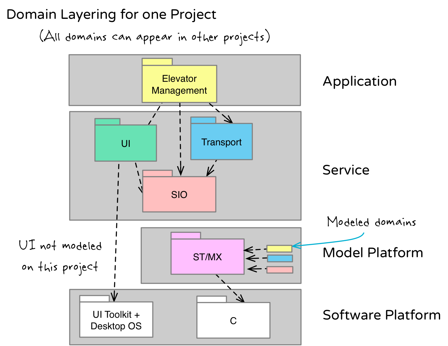
You can use non Executable UML languages but this will force you to deal with the model-to-code problem in some way or another Click To TweetDomain diagram layers
A domain diagram consists of four layers. So far we’ve explored the top two, application and service. I like to call those two layers the top half of the domain diagram. As an analyst/modeler it’s where I spend the bulk of my time on a project.
But to deliver running software, you will need to address the bottom two layers which complete your path to running code on a hardware platform. These two layers are the Model Platform and the Software Platform. We will explore both of these in more depth when we start generating code, but we must account for them in our domain diagram.
Model Platform
At this point we can go through the requirements and see that they are all accounted for in some domain. Well, not quite. We still have this key requirement of actually building the software and getting it to run on our computing platform. None of the domains we have so far address that minor detail 😉
Take SIO, for example. As close to the physical world boundary as it is, it is still just a bunch of xUML models (assuming we choose to model it with xUML). Just as we mapped an Open Door request in the Elevator Management domain to a Write Signal operation in SIO, we must map each of our model elements (Class, Attribute, State, Event) to some kind of code element.
This brings us to the Model Platform layer of our domain diagram which typically consists of a single Model Execution (MX) domain. The subject matter of this domain is Executable UML itself. It provides the execution framework that knows how to run the xUML models, store all of the class and instance data, traverse relationships, dispatch events and so forth. There is no magic to this particular domain. It just happens to be a different subject matter.
Fortunately for our project, the MX domain already exists as a fully implemented component. So, if we successfully populate this domain with all of our xUML models, by converting our models into a combination of code and configuration data as input to the MX domain, we should have a complete ball of executing code! This domain is populated with the help of a model compiler which reads the models and translates them into corresponding MX entities. There is nothing magical about a model compiler as all it does is instantiate elements in an MX domain.
The model execution elements and rules, by design, are a constant. They don’t vary from one implementation platform or application to another. But the implementation of those elements and rules can vary wildly. The model run-time component and code generated for an embedded micro-controller is quite different from that required to operate in a cloud environment, for example.
We need to be careful to choose (or otherwise build) an MX domain that suits our class of target platform. In our case we have chosen an MX domain that runs well on a single board micro-controller, which does suit our needs (with the exception of the administrative user interface).
Software Platform
Unlike the other three layers, the domains are already fully specified and available on the hardware platform, so there is no need to model them. Typical platform domains are operating systems, math libraries, databases, UI toolkits, network components and so forth. A programming language is also a software platform domain. Is a programming language a domain? The quick answer is yes, but if you are not so sure, go back to our definition in the previous installment and think about it. There’s really nothing special about a programming language as a subject matter.
Our Software Platform is fairly simple. On the administrative UI side, we need a UI toolkit of some sort and whatever operating system that runs on. For the rest, we can just run everything on the MX domain which, itself is built on C. It does not rely on any kind of operating system.
Layer summary
The domain diagram depicts ALL of the software necessary for a project. It lays out an unbroken path from your application subject matter through all the layers of abstraction necessary to reach your coded software platform elements. There should be no mysterious gaps!
The top two layers of an domain diagram, application and service, are platform independent. You should be able to implement those two layers on diverse platforms without making ANY changes to the models themselves. (That’s if you are using xUML). If you specify a domain using some other language it depends on that language’s inherent platform independence features.
The top layer is your application. It defines the business purpose of your system. It’s content, by definition, is highly specific to your application.
Domains in the second layer, services, are general purpose and should be configurable to work with a variety of applications. That said, the content you build into your services should be just enough to support your particular application (and, to some degree, its anticipated expansion).
The third layer, Model Platform, is specific to a class of applications and implementation environments. You could have a model platform that is single threaded, single tasking or one that is distributed and fault tolerant or one that supports mobile platforms. I’ve heard people falsely claim that xUML requires a unique model execution domain for each project. This has not been the case at all in my experience.
Finally, the fourth layer, the Software Platform defines the implementation components used to construct the Model Platform as well as any required by non-xUML domains.
What about deployment?
One final note about domains; the domain diagram does not specify or even imply any particular deployment. You could run all the domains in a single threaded loop or you could put each one in its own execution unit such as a task or a thread. Or you could put each instance of each class of each domain in its own processor in a massively parallel implementation. (These are extremes for illustration, but the xUML language is expressly designed to support all of these possibilities). You can, of course, specify deployment relative to a domain diagram (or any other diagram) in a separate marking model.
Coming up next
In our next installment we will dive into the Elevator Application and begin building its class model and clarifying our service domain requirements.
I help agile software teams succeed with requirements analysis, domain definition, platform independent, executable modeling and high quality code generation. Other websites: executableuml.org, modelstocode.com

Hello, your tutorial is very interesting,
however I believe your architecture is too naïve: the domain (here elevator management) naturally does not depend on the UI, nor the UI on the IO’s. This would break the independence principle. Instead, one should apply inversion of dependency and create interface packages : the IO, the UI and the domain are all independent and depend only on interfaces that may be implemented by a variety of GUI’s. What if i want to control the elevator tomorrow through my IPhone. This is usually called the W-architecture.
Best regards,
Thierry
Hi Thierry and thanks for taking the time to read and comment. The domain diagram probably would be a naïve architecture, but happily it is not meant to be an architecture at all. I realize that the term “architecture” is a bit overloaded, so I am not exactly sure of your intended meaning. (I tried googling W-Architecture and didn’t find it, not in the software context anyway 😉 Link? In my experience, that term generally is used in a design context and in our case, at least for the top two layers, we are avoiding any design specifics.
As far as dependence goes, I would say that, in the context of our project, the Elevator domain is dependent on the availability of the UI capabilities, though it is not influenced by the design of those capabilities. Outside of a project context, you could imagine the domains as independent subject matters. But once combined together to define a system, you need to know which domain influences the requirements of another. I wouldn’t look through the Mac OS Cocoa library to learn anything about how the elevators should behave. But I would certainly use my knowledge of the elevator domain content to decide which Cocoa (since you mentioned the iPhone!) features might be relevant and useful. And I would certainly base the size and extent of the SIO domain on what sorts of events and sensor based attribute values are required by the Elevator domain.
By isolating the UI from the application domain we do gain the ability to support a wide variety of UI technologies, including the use of the iPhone as an interface device. I don’t see anything in the domain chart precluding usage of an iPhone.
Just in case of TL;DR
“… I would certainly use my knowledge of the elevator domain content to decide which Cocoa (since you mentioned the iPhone!) features might be relevant and useful.”
Perfect! The arrow shows “flow of requirements”. Precice interface details would only distract from the objective of analysis.
Hi Thierry,
The Bridge between two domains is precisely what your are asking for. It’s a formal realization of the Dependency inversion principle acting as a duplex conduit that exposes one interface to each domain. Each interface uses the same sematics as the domain to which the interface is exposed. The role of the Bridge is thus to translate between the two interfaces and, consequently, connect the two domains.
A consequence of this is that replacing a GUI-domain with e.g. a Console/CLI-domain only requires updates to the Bridge – mostly the HMI-side of the bridge.
Cheers
Nils
I suggest you look at Dependency injection and Inversion of Control
https://en.wikipedia.org/wiki/Inversion_of_control
I do agree in the end, the GUI system needs to know about the buttons and what not, but the elevator management system, no. It just needs to know there are services available, through neutral interfaces, that may provide control and feedback.
Same for the IO’s.
Your designs will be much easier to maintain, and, most importantly, to generate.
Thierry, you seem to miss the point of analysis. The analysis activity focusses on functional requirements of a system. This particular approach (Shlaer-Mellor) suggests using domain semantics as basis for of divide and concur.
You concerns are valid and importent for non-functional requirements that the software engineer activity addresses in the model compiler.
“… motor control isn’t exactly an Elevator specific *function*.” Oops. More consistently, the language of motor control is not naturally spoken by users of elevators.
I’l like to emphasize how important domain analysis is to the success of a modeling effort for a system. It is too often overlooked in our rush to “show progress” on a project. Getting the subject matter split along with describing the requirements dependencies between domains is critical to containing the analysis and insuring the domains are cohesive. This topic is too often overlooked or under-emphasized in our discussions of executable modeling.
On the topic of handling a UI domain, a couple of points. I agree with Thierry that UML (and, in my case, always xUML) is not necessarily the best tool to use in all cases. Of course, no tool is. In some cases I am happy to just provide a UI expert with the application requirements (after at least building a class model of the app) and have them go to it with whatever tool/frameworks are at hand. But I tend to work mission-safety critical systems which often have UI components that do not lend themselves to an out of the box UI toolkit solution. Fighter jets, smart cars, medical devices, etc. A particular helicopter communications interface I worked on comes to mind and we definitely benefited from a complete xUML model (classes, states, actions) to sort out policies for managing display and selections on specialized hardware on an avionics network. A very primitive set of UI functions were available, but that didn’t help us think through and document a coherent and consistent model of interaction from which we could generate high performance code. So, sometimes, xUML is the best solution for a UI. But, like Thierry says, pick the best tool for the job. That’s why I like doing the domain analysis first and choosing the modeling languages or toolkits second as the project demands.