In the previous installment, we laid the groundwork for specifying our Elevator System with a domain diagram. Now we will begin modeling within the application domain titled “Elevator Management”.
The focus of today’s lesson is:
- How to get started modeling an application that interacts with the physical world
- See how non-model sketches, free from the usual modeling constraints, can help you think about a problem and discover what you need to model
- Learn how to model data concretely without biasing yourself toward any particular programming language or programming style (object, functional, etc.).
- We will also begin exploring the yin-yang interplay between data and logic modeling
When modeling in any domain it is critical to have inclusion/exclusion criteria at the outset: know which kinds of details should be modeled and which ones are to be ignored. Otherwise, you’ll never know when you’re done modeling. In the Elevator Management domain we include anything application specific necessary to manage elevator behavior. We exclude anything that can be modeled as a general purpose service. We’ve decided, for example, to exclude the details of motor feedback control since we believe that this can be handled in a general purpose manner which can be configured to support our elevator specific behavior. In practice, you sometimes need to adjust your inclusion/exclusion criteria as you go when you discover a general purpose solution of enough magnitude that it warrants its own domain.
So we’re going to model the elevator specific stuff only. This includes activity like, is the door to cabin 6 open? What floor is cabin 3 going to? Is floor 5 available for access by cabin 2? Which floors are requesting a cabin in the up direction right now? Which shafts are in service? Button status (or even the existence of buttons) is excluded from this domain, as well as motor control and sensors and actuators. These details are quite important, but they will be handled elsewhere.
To accomplish this, our model must capture key physical aspects of the elevator system. We can track the status of physical classes and control them.
How do we get started? One old approach (I remember it being touted back in the 80’s!) is to write descriptive statements in natural language and then pick out the nouns. Anything that helps you get started is great, but we will soon find that we can’t restrict our thinking to the nouns. Instead, what usually works best for me, is to sketch some detailed, realistic scenarios or use cases. I make a point of NOT using UML in my sketches to keep the focus on observation and discovery. You learn a lot by concentrating exclusively on your subject matter and absorbing it as-is rather than fumbling about trying to cast it into modeling artifact or premature generalization. The real world doesn’t care about your standards and pattern libraries. It is what it is. So, quite literally, think outside the boxes!
You may want to avoid UML (or any other 'formal' language) when sketching scenarios for your system. The focus is on discovering the key parts of the system, not worrying about the syntax. Think outside the boxes (literally) Click To TweetFirst scenario sketch
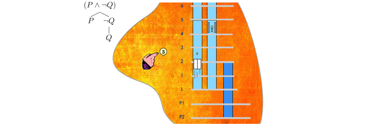
Our first simple sketch might look like this:
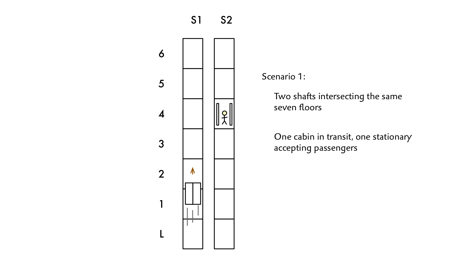
Note that I have named the shafts. There’s no call for this in the requirements, but it’s going to be difficult to describe scenarios in detail without some way of telling one shaft apart from another! When there is no real world naming scheme for a group of things it is the analyst’s job to introduce one.
Now we start looking for classes, attributes and relationships. The classes that jump right out are physical entities such as Door, Cabin and Shaft. Should floor be modeled as a class? Or should it just an attribute of a Cabin? We’ll come back to that. (I put class names in title caps so that it’s clear when I am referring to a modeled term vs. one that is informal).
There seems to be a one to one relationship between Shaft and Cabin and no obvious attributes on Shaft, so do we need both of them? When I’m not sure, I generally take the approach of modeling both. In my experience, the more closely you match the world you are modeling the more likely you are to get it right in the code. Clearly, there is a limit to this thinking. You don’t need to model each bolt holding the cabin together since they are unlikely to be of any significance to the software.
The observation that a Shaft may or may not be in service is relevant and the concept of a Shaft can be useful for establishing the range of floors that may be accessed by a Cabin. When in doubt about the need for a given class, leave it in to start out. It’s easy enough to remove it later if you don’t need it. Trying to solve a problem with inadequate semantics, on the other hand, is where you can get bogged down.
Articulate modeling
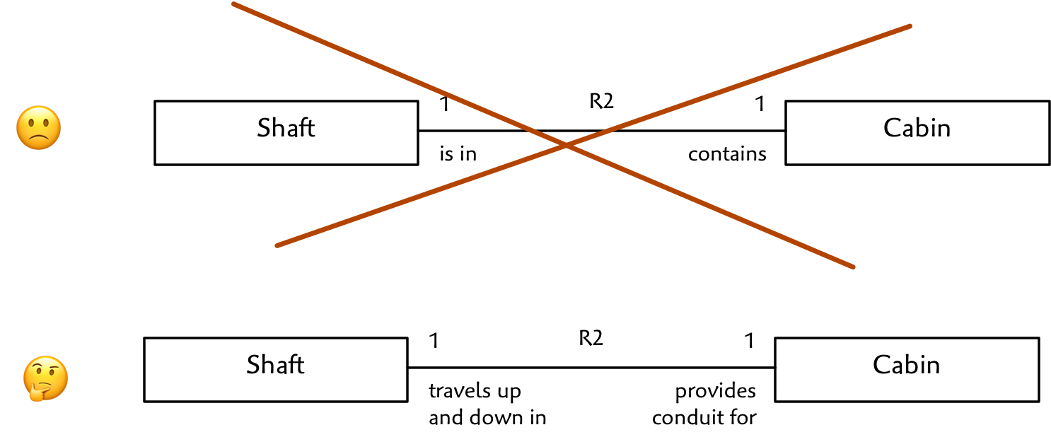
Let’s try to model the relationship between a Cabin and a Shaft. At first, it is tempting to write something like this:
Cabin is in Shaft / Shaft contains Cabin
True, but it doesn’t tell us much. It is better to write something that suggests the real purpose behind the “containment” idea. More like this:
Cabin “travels up and down” Shaft / Shaft “is conduit for travel of”. Higher precision writing leads you to ask key questions about the multiplicity and conditionality of the relationship which often exposes corner cases. This practice also helps you unwind what appears at first to be a complex relationship with undefinable multiplicity into distinct well defined associations. The multiplicities are quite different for Person owns Car / Car is owned by Person vs. Person is driving Car / Car is being driven by Person for example. Or Parameter Set configures Station / Station is currently configured by Parameter Set vs. Station will initialize with Parameter Set / Parameter Set initializes Station.
So when I say Cabin travels up and down one Shaft, the question presents itself, could there be more than one? What would that mean?
For example, could two Shafts be stacked on top of one another? Might two Cabins travel within the same Shaft, as long as they don’t try to occupy the same space at the same time? Is an aligned vertical path the same thing as a Shaft? So if two Shafts are stacked are they distinct Shafts or really the same thing? Ultimately, we want to answer this in the context of our requirements. Often we need to ask more questions to clarify our needs.
Choosing good names for classes and relationships helps you to ask key questions about their multiplicity and conditionality which often exposes corner cases. Click To TweetFor our purposes, we find, not surprisingly, that it is too dangerous to deal with multiple Cabins in the same Shaft. But it could certainly be the case that Shafts are stacked vertically. Can a Shaft be empty? Can a Cabin exist without a Shaft? Strange questions to ask, but it is precisely because a case is absurd that we need to identify it early on. It’s our all too human focus on the common, reasonable cases combined with pressure to develop quickly that blinds us to predictable and sometimes dangerous faults. Here at the analysis stage, articulate modeling gives us an opportunity to exclude dangerous cases before they ever get a chance to infect our code.
All that said, we decide to make it our policy that a Shaft provides travel for only one Cabin and that a Cabin cannot physically pass through one Shaft and into another stacked on top. In the odd case where one Shaft is physically stacked on top of another, each Shaft will manage its own Cabin. This decision is based on our perception of requirements and knowledge of the physical limitations of our equipment. This decision will be documented as part of the R2 association description.
Door
Now, what about the door? How many doors can we have on a Cabin? What is meant by door? Is each side a door, or the whole assembly? Is there an opening on each side or just the front?
After a discussion with the product owner we find that our system need not support front and back doors. So, there will be only one opening on each Cabin. Further, we find that there are doors that move with the Cabin and doors at each floor/shaft opening. But the floor/shaft doors are not under software control. The Cabin door opens and physically latches to the floor/shaft door causing it to open and close. So we don’t really need to worry about those. It is just the Cabin door that we control. Therefore, this model should be correct:
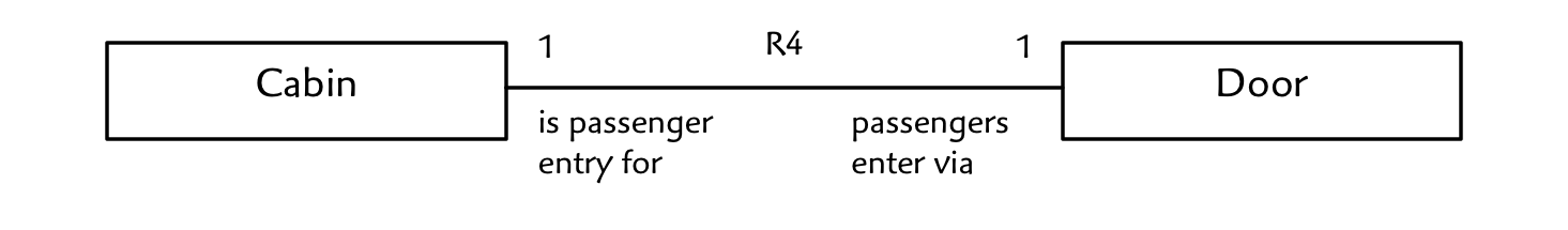
Again, note that we have avoided anything vague like “Cabin has Door”.
Agile modeling
Note that we are making an agile modeling decision here. We could build a model that handles all sorts of Door/Cabin arrangements, but we have decided to formalize the simple case since it satisfies our requirements. The choice of modeling scope is based on numerous project variables. But it is often a good idea to be satisfied with the simple case so that you can spend more time on the rest of the model.
Model vs. Implementation Class
Before moving on to modeling floor as an attribute or a class, we need to consider what exactly is a class in xUML. The concept of a class in an object oriented programming language is generally understood. But we’re not programming, so there is no particular reason why OO programming principles should apply. And, from an analysis/modeling perspective, we shouldn’t care whether or not any generated (or handwritten) code produced from the models is object-oriented at all. We certainly shouldn’t build in any assumption that a language like C++ or Java will be used. (In at least one case we’ve generated assembler as the direct output of our models and, for embedded applications, C is often suitable). And if you want to write code in a functional style, why should the model tell you any different? The model should just describe the real (or abstract) world with respect to your requirements and let the programmer make the programming decisions.
A Class in Executable UML
For our purposes, a class is a set of physical or abstract elements such that each element has the same characteristics, behavior and is subject to the same constraints, rules and policies. So if we declare a “Cabin” class, we are saying that no instance of Cabin is treated specially. They all do the same thing. No attribute of Cabin is “not applicable”, because that would make it special!
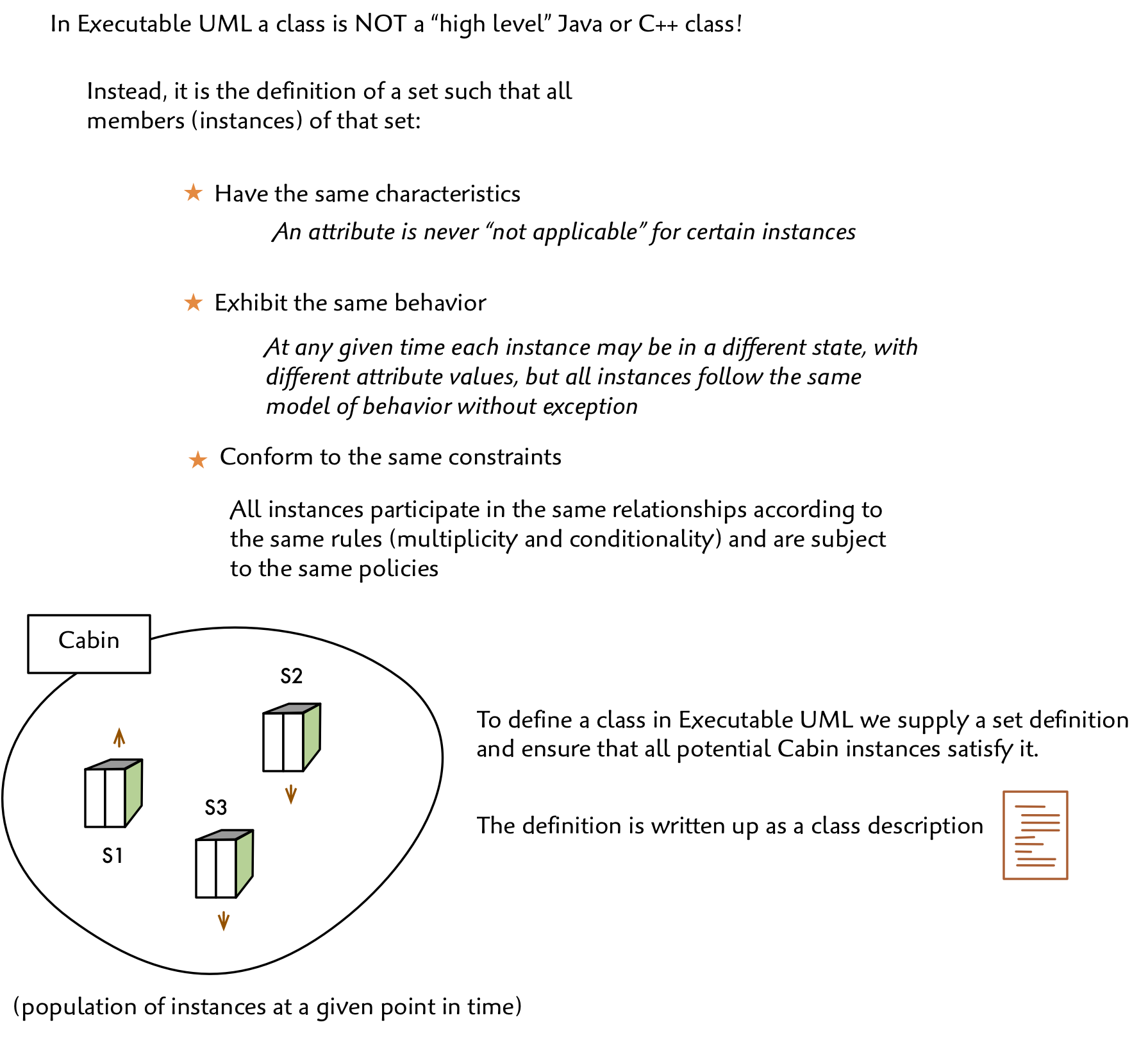
This classification is critical to simplifying the behavioral components (states and action language) later on. If all instances are the same, then we won’t be needing any special case logic. And, if we do, we need to go back and correct the class model.
So, instead of thinking of a modeled class as some sort of “high level” OO programming language class, we take a more mathematical perspective and treat it as a simple set definition with the commonality criteria just described.
So, from an analysis perspective, we observe that the world we seek to control consists of discrete entities with both synchronous and asynchronous behavior. This world is bound together by numerous constraints on data and relationships among the entities. Our model seeks to capture the entities, data, relationships and all constraints.
So that’s why we model with classes, attributes and relationships. Not for the object oriented programming advantages such as information hiding, code reuse and encapsulation.
Now let’s get back to our model…
Floors
Now let’s figure out what to do about floors. Looking at our simple sketch it might be tempting to think of floor as an attribute’s data type. Spoiler: it turns out to be a bad strategy, but let’s see why.
Make it a data type
An attribute such as Cabin.Location could be assigned a Floor Level type that we could define. Now at the model level, a type is another set definition that establishes the finite set of values that might be assigned to that attribute for any given class instance. For Floor, we can see that it is not the set of positive integers or even integers at all. (Note: Mathematically, the set of integers is infinite, but we can safely assume that we are targeting a computing platform which deals exclusively in finite sets. Therefore, we assume that all of our types are finite sets). Floors have names like L and P1, P2, etc. Some elevators might have fancy names like Penthouse or Lobby. So we have some sort of text type which we will want to limit to some length of characters, say 20. We don’t generally use “String” as that is an implementation type. It’s rare that you have a text attribute that doesn’t impose some kind of constraint on which characters and patterns are acceptable. In our case we can define a type called Level Name that imposes such constraints. (I generally use a regular expression to specify text types).
Now let’s take a look at a more complex use case.
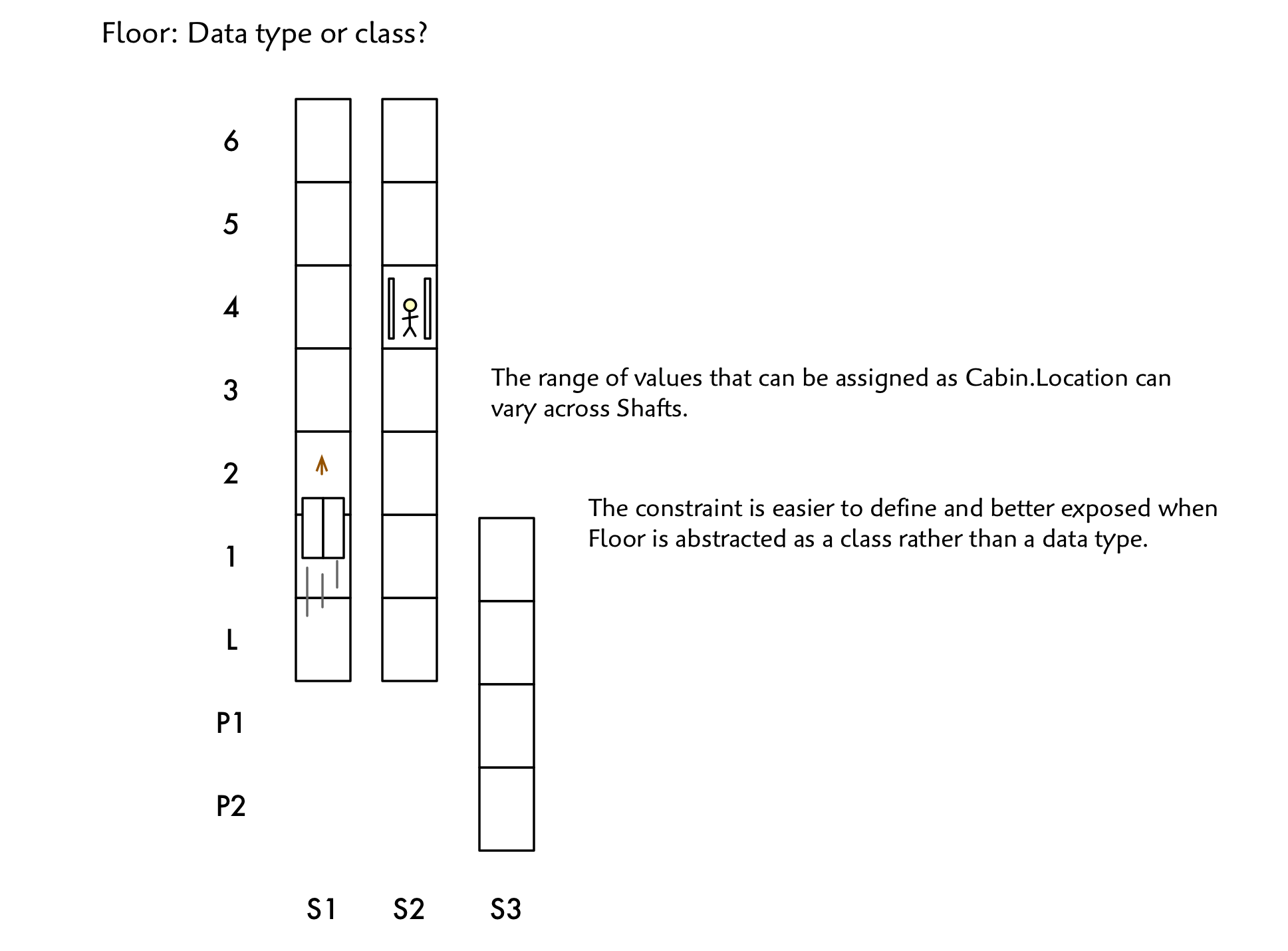
Floor: Type or Class?
Notice a subtle constraint. A Cabin in Shafts 1 and 2 is constrained to only have certain values in its Location attribute. A Cabin in Shaft 3 has a different range. We could write a constraint on top of our model, but that could be problematic to maintain. Remember that our elevator can be re-configured to lock out certain ranges of floors for sets of Shafts.
Make it a class
So it turns out that we’ll get a simpler and more constrained model that better matches reality if we capture Floor as a class and model its not-so-simple relationships with Shaft.
Our Floor class provides an opportunity to introduce Executable UML attributes. In this example we see two attributes. We capture the floor name, “P1”, “L”, “1”, “2”, etc. with the Name attribute typed as Level Name and marked as an identifier with the {I} tag. We also add the vertical Height attribute typed as Distance.
Model level vs. implementation types
Just to be clear, every attribute has a model level data type. We don’t use types like double or Uint8 as these are clearly implementation specific. Instead we define platform independent types such as Name, Speed, Pressure, Count, etc. In all cases, a type defines a finite set of assignable values.
The identifier tag (uniqueness constraint)
Now we turn to Executable UML’s identifier {I} attribute tag. An identifier is a set of one or more attributes defined on the same class such that supplying a corresponding set of values for those attributes yields either one or zero instance of that class.
Let’s say that we have a population of Floor instances and are given the value “P1”. Since Floor.Name constitutes an identifier (which just happens to consist of only one attribute) we will either find a single corresponding instance or we won’t.
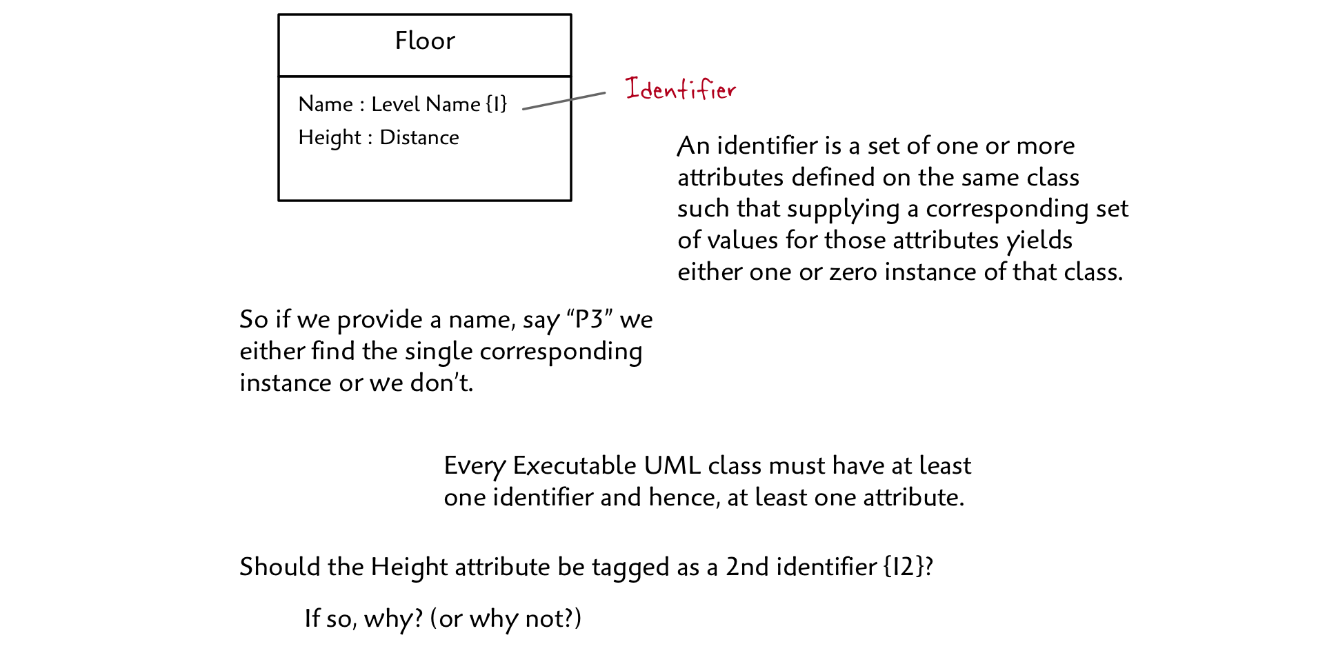
Since Floor.Height is not marked as part of any identifier, the model effectively says that more than one distinct Floor instance might be at the same height. Is that right???
You may wonder why we designate identifiers. Three reasons:
- To express uniqueness as a constraint. This turns out to be a powerful tool for exposing corner cases. Is it meaningful for two distinct Floors to have the same height? From other applications: Can two recorded events occur at the same point in time (timestamp as an identifier)? Can two navigation markers be at the same location (latitude, longitude as an identifier). Seriously, I can’t tell you how many times throughout my career that I’ve triggered extensive debates among subject matter experts merely by suggesting an identifier!
- To help analyze dependencies among attributes in the same class and ensure data integrity. (If I change the value of this attribute does it influence the current value or range of allowable values for that attribute?)
- To provide a way of naming instances uniquely so that we can refer to them across associations. We don’t use handles, links or pointers in Executable UML as these are considered implementation artifacts. Relational theory correlates data using sets and functions only.
Of course, the programmer (or code generator) is free to choose whatever handles, indexes, hashes or other mechanisms are appropriate to implement the modeled uniqueness constraint. A variety of such mechanisms are utilized in our book Models to Code.
By the way, let’s go ahead and designate the Floor.Height attribute as an identifier. Our policy will be that if two Floors in our building are at the same height, even if serviced by different groups of Shafts in horizontally separate parts of the building, we’ll want to name them the same to avoid any confusion. If our policy turns out to be a bad idea, we’ll have to go back and change the model accordingly!
Floors and Shafts
Now that we’ve modeled Floor as a class, we can think about how Floors and Shafts relate. It helps to look at a possible real world scenario.

We can see from our figure that a Floor intersects multiple Shafts and that a Shaft intersects multiple floors. The intersection of a Floor and a Shaft yields a, well, we don’t have a name for it, so let’s just call it a Shaft-Floor Intersection for now.
We’ll ignore the attributes for a moment and focus on the association as shown:
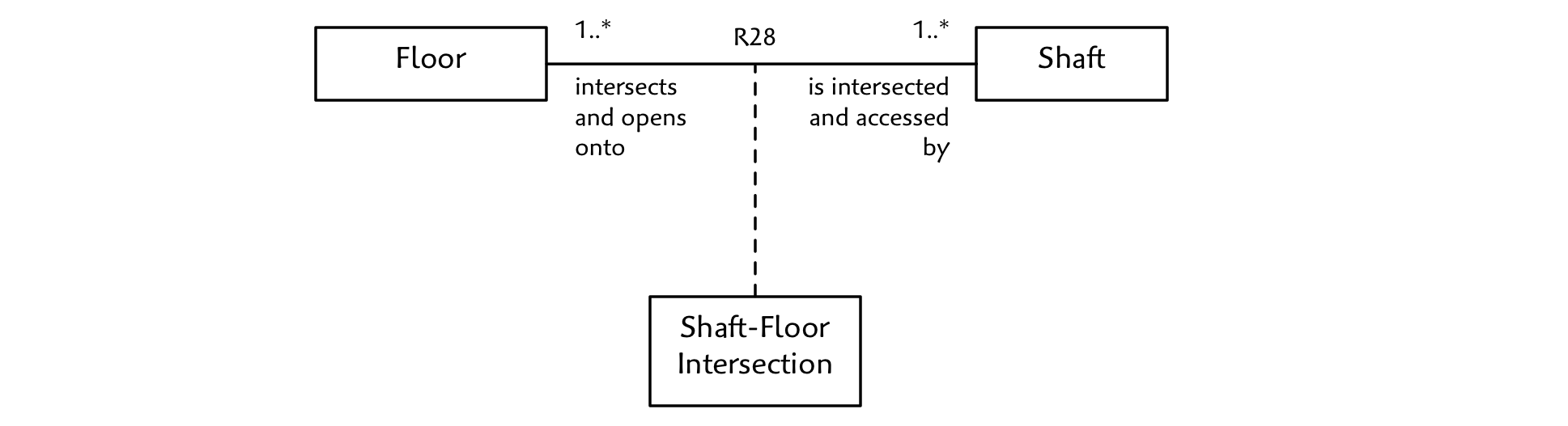
Again, we must be careful in our naming since the association could have different meanings impacting multiplicity and conditionality.
Consider Shaft physically intersects/is physically intersected by Floor. But wait, do we require that there be an opening at the intersection? Imagine a Shaft that passes through several Floors but does not provide an opening for the Doors. Is this possible? If so, physically intersects does not mean the same thing as accesses floor at.
It seems reasonable that if a Shaft passes a Floor, but does not have a physical opening, we can disregard that Floor. In other words, we only care about those Floors we can access. Thus, we can rename the association to can access.
We must be careful about what we mean by this. We’ll say that can access means that the Cabin could stop there, open the doors and let people in and out. It could also be that we choose to block that Floor for a given Shaft as part of our building configuration except in the case of emergency and then maybe provide access if floor access is reconfigured. So our association does not necessarily mean provides service to.
Now let’s consider the multiplicity and conditionality.
To be useful, a Shaft must provide access to at least one Floor (and certainly two!). This means that, when configuring floor access for a Shaft, you cannot block off all Floors except for one. Instead, you would just take the Shaft out of service.
Now we don’t have “2” as an option, though the constraint is important and we will handle that later. For now, “many” is good enough. From the opposite perspective, a Floor that cannot be accessed is of no interest. Still it seems plausible that at some point we may want to block all elevator access to one or more Floors. Note that had we modeled physically intersects instead, we would insist that a Floor meet with at least one Shaft otherwise it would be of no interest in our system! This opens up the question of whether we’ll need to model both associations somehow. This is something we’ll revisit in the next installment.
Let’s take a closer look at the attributes and how they are used to formalize the association.
Let’s start with the Shaft class. We’ve assigned an arbitrary identifier so that we can name Shafts 1, 2, …
Note the type Nominal. It’s a number from 1 to the system maximum integer. They type is called “Nominal” because it is a number used purely for naming. No math operations are supported on this type. And that is another important idea, a model level data type is not just a set of values, it is also a set of supported operations. By policy we will ensure that these are unique so that no two Shafts share the same ID value.
Since a Shaft may or may not be in service at a given point in time (it’s in the requirements), I’ve added a boolean In service attribute.
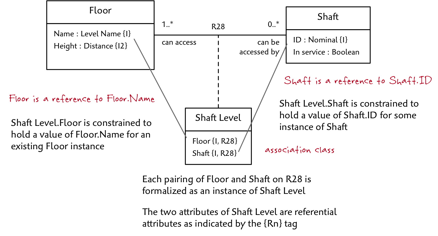
The Shaft Level association class represents potential shaft access and has two referential attributes tagged as R28. Consider Shaft Level.Floor. It refers to the Floor.Name attribute along R28. The referential constraint indicates that any value of Floor for an instance of Shaft Level must match a value of Floor.Name for some existing instance of Floor. Since this means that the data type of Shaft Level.Floor must be the same as Floor.Name, we omit the specification of the type in the Shaft Level class. Nonetheless, a referential attribute does have a type just like any other attribute, but we don’t show it since it can be determined by following the reference.
Once you get used to reading Executable UML class diagrams, and especially if you use consistent naming conventions, it is almost always obvious what attribute is being referenced by a referential attribute. Just to be sure, however, the specific reference is always documented in the model descriptions that accompany the diagram.
An association class will always hold two references: one to each participating class on the formalized association. When the association is many-to-many (regardless of any zeroes), both references are taken together to form an identifier of the association class. In this case, Shaft Level has one identifier Floor + Shaft.
We can use tables to help visualize how all this works with our example scenario:
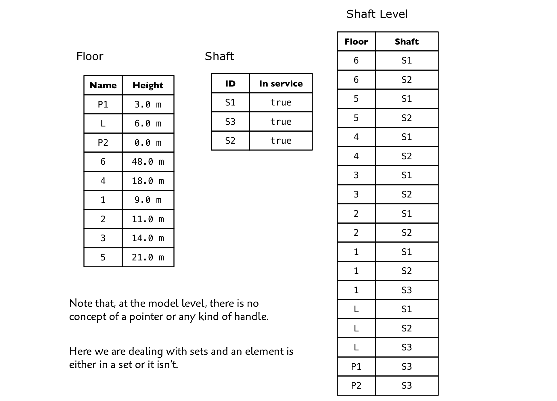
It should now be obvious that both Floor and Shaft must be combined to form the Shaft Level identifier. If you supply only a Floor or a Shaft value you might find multiple matching instances. But if you provide both a Floor and a Shaft value, you will get either one or zero instance. In other words, either a Floor can be accessed by a Shaft or it can’t!
Tables! Oh N 😮 sql!!!
Don’t be alarmed by the presence of tables. There is no suggestion that the data be stored that way in the implementation. But we do need an unambiguous way of thinking about instance data and how instances are related irrespective of any particular implementation. The best way to do this is to take a minimalistic mathematical approach. Fortunately, there is a branch of mathematics that does this and it’s called relational theory. This has nothing to do with relational databases or SQL which constitutes a particular implementation technology. Here we are concerned only with the theory which is an extension of set theory, functions and predicate logic. In reality the tables are just visualizations of underlying functions and sets. The visualization breaks down when we consider empty sets where there are zero attributes, zero instances or both! But these cases only arise in the action language when we process our table data so we’ll take a look at those in a future installment.
When we look at a class without considering any particular population we can construct a table header. To do this, we name the table with the class name and then create a column for each attribute-type pair. In reality, the table header is just a way of visualizing a set of ordered pairs.
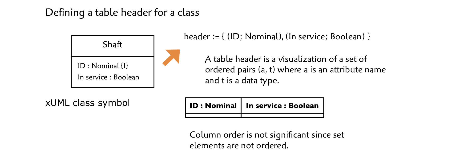
Set elements are not ordered, so there is no significance to the order in which you create the columns.
To populate the table, we create a row for each instance. Consider the Shaft table. In our example we have three Shafts represented as shown:
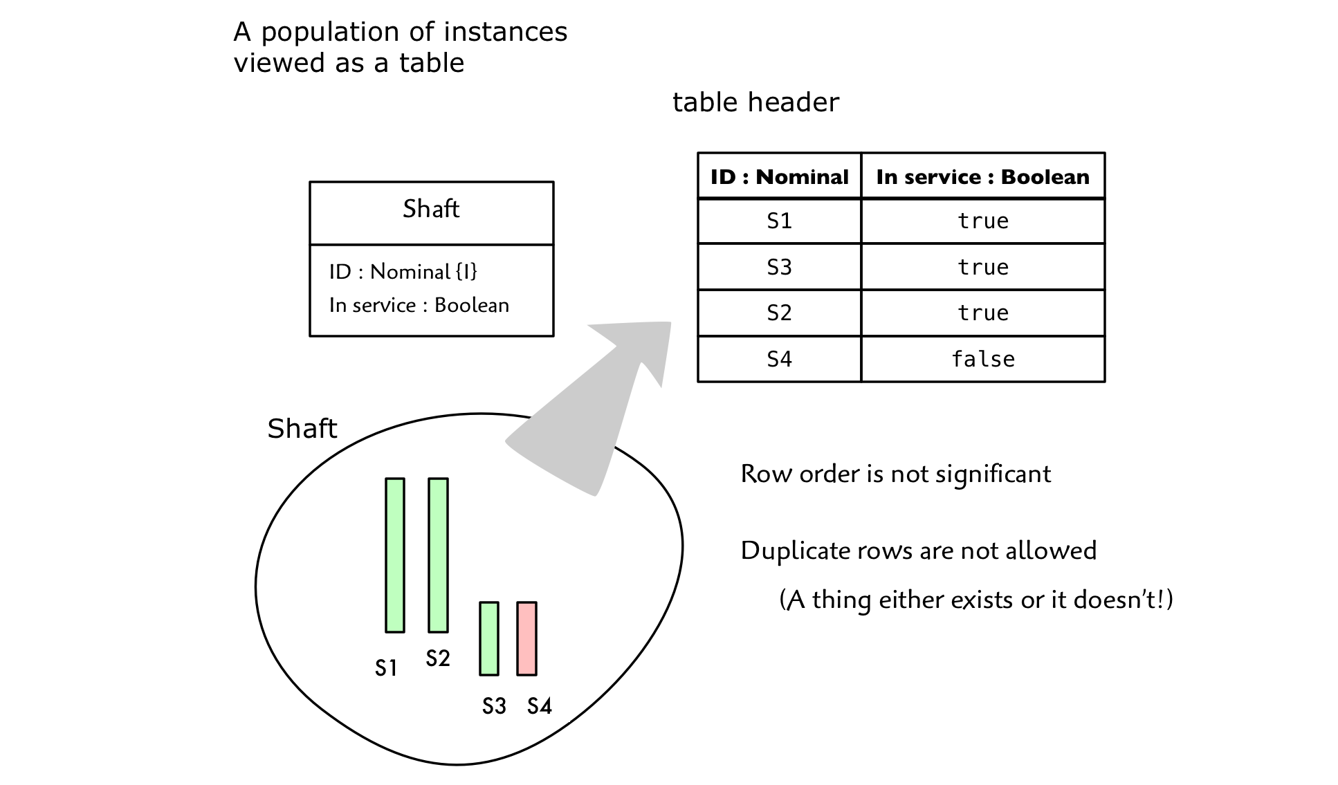
So for each instance we must supply a value for every attribute. Each value is constrained to be selected from the set defined by the attribute’s associated data type.
The instance population of a given class is also a set which means that 1) no instance can be duplicated and 2) there is no ordering. So you cannot have duplicate rows and row order is not significant.
Tables and logic
But there’s more to class modeling than just structuring data. If that’s all you are doing, then there isn’t much value in building class models. Executable UML class models really shine as powerful expressions of rules and constraints in your modeled subject matter. In other words, we aren’t just modeling data, we’re modeling logic. Done right, the data model is really just a byproduct of a logic model.
In logic, a proposition is a statement that evaluates to either true or false. “Shaft S7 is out of service” is a proposition. At a given time, the statement is either true or false. A predicate, on the other hand, is a statement that can be reduced to a proposition if enough data is supplied. “Shaft s has service status i” cannot be evaluated as true/false unless its two variables, s and i are supplied with values. You can think of a predicate as a function taking some number of parameters and returning a boolean result. In fact, a proposition is just a simple case of a predicate requiring zero parameters.

Now consider our Shaft class. It defines a predicate with two variables corresponding to the class’s attributes reading “An instance of Shaft has a value s of type Nominal for ID and a value of i type Boolean for In service value.” (We can choose any name for the variables we like as long as they are distinct). Also, we’ve included the data type restriction on value assignment which I omitted earlier for simplification.
So how is a predicate useful?
Looking at our predicate without supplying any values, we are making the statement that every Shaft has an ID and a service status. The predicate holds for all possible populations of Shaft.
In a running system at a given point in time, we might want to know: “Is Shaft S1 out of service right now?” To answer the question, we look for the row with the values S1 and False in the appropriate columns. If none is found, we know that the proposition is false. (It may be false because S1 doesn’t exist at all, but it is false nonetheless).
In fact, the population of a class is the set of all true propositions corresponding to the class predicate. Any propositions not present in the population are considered false.
By applying the identity constraint described earlier, we can use the shorter predicate: “There exists a Shaft with ID i”. We supply a value for i and, if no result is found, the predicate evaluates to false, otherwise true.
I realize that this focus on logic probably doesn’t seem so impressive on a single class such as Shaft. But more sophisticated predicates can be combined systematically across multiple classes and relationships. Thus, a class model lets us construct some rather sophisticated logical statements that can be tested. Logical statements that can be proven are particularly helpful in systems were we care about functional safety. Wouldn’t it be nice if we could prove a system correct before generating/writing the code? This is one of the reasons that Executable UML is particularly useful in mission/safety critical systems.
To recap, Executable UML class models are illustrated with UML symbology, but are defined on relational theory rather than vague notions of “high level” object oriented programming. This puts us in a position to leverage powerful concepts such as predicate logic. This, in turn, helps us build more reliable systems.
Executable UML class models are illustrated with UML symbology, but are defined on relational theory rather than vague notions of high level OO programming. This allows us to leverage powerful concepts such as predicate logic. Click To TweetWe’ll revisit the theoretical aspects of our modeling language as we develop our model, but let’s get back to building our application!
What about behavior? Requesting a stop
Up until this point I haven’t talked about dynamic behavior. How do we deliver a Cabin to the next Floor? How do we decide where to go? Even though we don’t model behavior in a class model, we frequently think about it. That’s because we must ensure that we’ve captured all of the information, rules and constraints necessary support the required system behavior.
We know that someone will request a Floor from inside the Cabin. We’ll call this a stop request since the passenger wants to stop somewhere. This is not to be confused with an up/down request from a Floor which we will handle in the next installment.
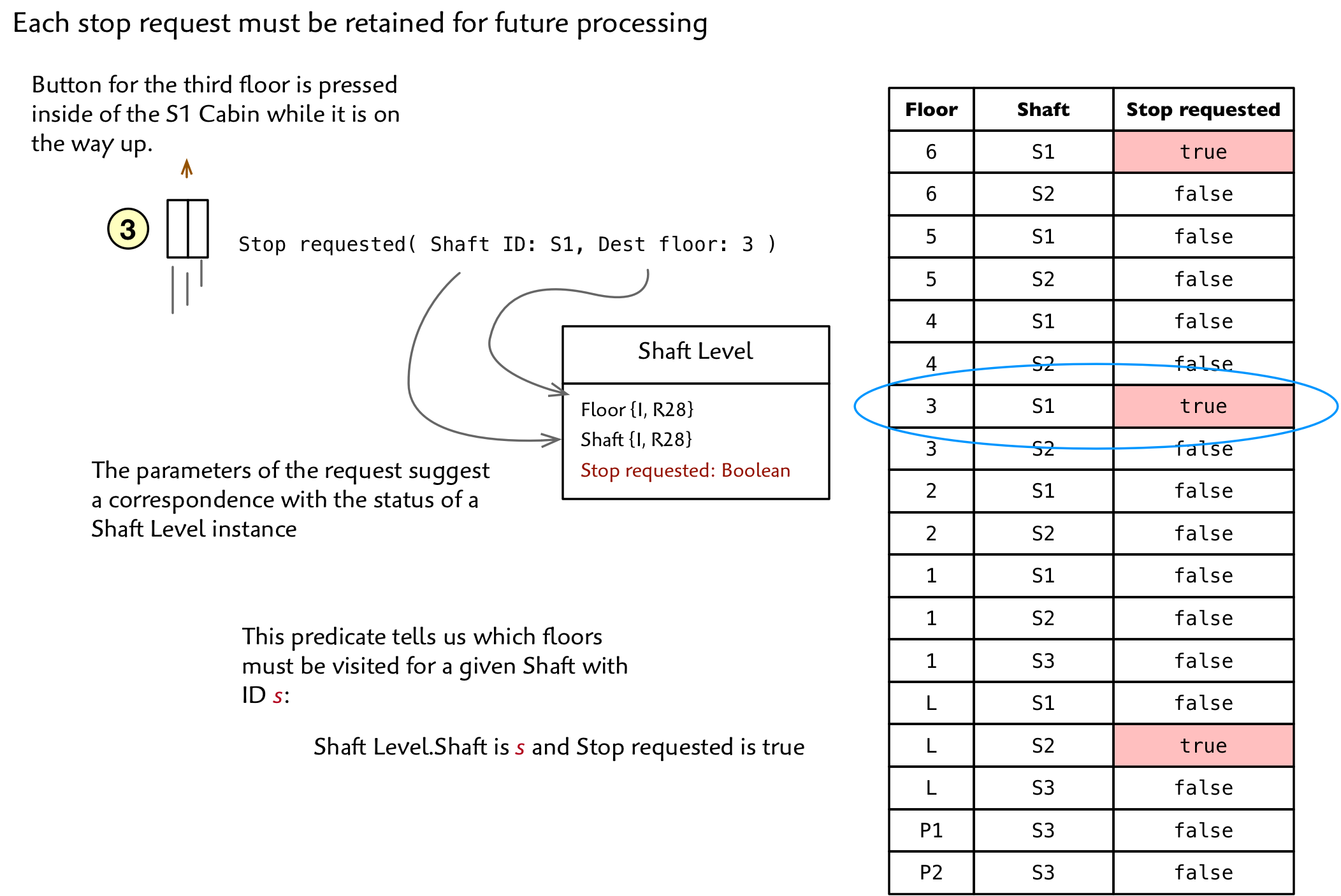
Let’s say that the 3 button is pressed from within the moving Cabin in Shaft S1. Since we exclude UI details in this domain, we just see an abstract Stop requested( Shaft:S1, Dest floor:3).
But what do we do when a Stop requested event occurs? If a Cabin is at rest and has nothing else to do, it will service the request immediately. But if it is busy, moving toward a different Floor, waiting for the Door to close, etc., the request has to sit for a while before being serviced.
In Executable UML, all persistent data is formalized in the class model. So we need to examine the stop request and ask ourselves what it represents and where it should live in the model.
We notice that the Stop requested elements correspond directly to the attributes of a Shaft Level. At any given time some subset of the Shaft Levels are requested. One solution is to add a boolean attribute to Shaft Level. When a Stop requested event is issued, we flip the corresponding instance to true. Then when we get around to servicing the request we can toggle it back to false.
)
For now, I will leave it as a student exercise to consider the other possible solution 😉
Problems with our model
Here is our complete model up to this point:
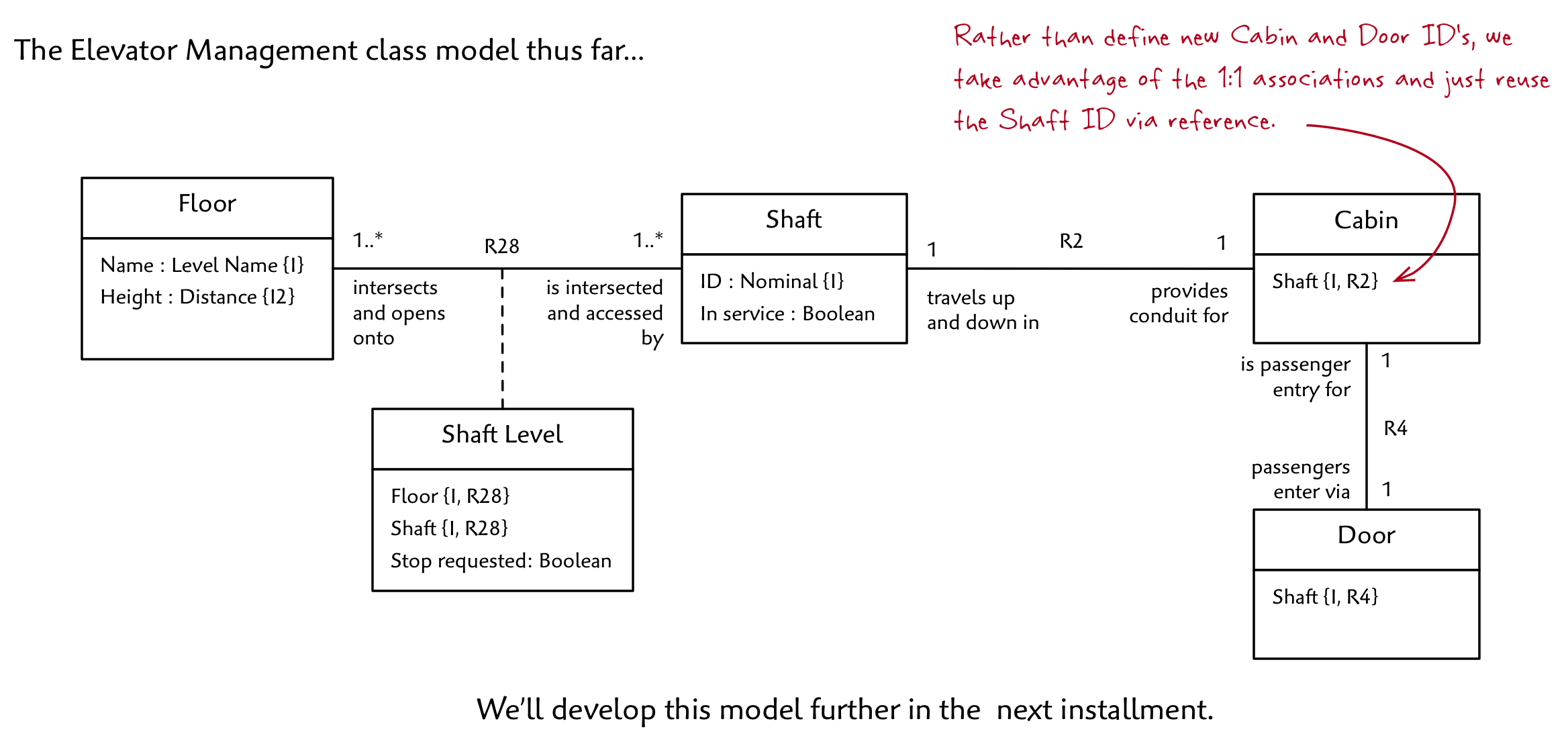
A good way to evaluate a class model is to see if it answers all the questions (provides all the predicates) that you’ll need while the application is running.
For example: Does the model tell us the current location of the Cabin? Do we have enough information to support the ability to restrict access to certain Floors for a group of Shafts? Do we know when to close the Door if it is open?
If not, what information is missing? How might we add it in?
Also, note that the aforementioned attribute Cabin.Location isn’t shown. That’s because we decided to model Floor as a class which means that we must use a referential attribute and hence an association along the lines of Cabin is located at ??? Should we create an association to Floor or to Shaft Level? Which would you choose and why? Or would you do it a different way altogether?
I’ll reveal my choice in next installment where we’ll complete the class model and answer (hopefully) all the questions that must be answered to satisfy our requirements!
I help agile software teams succeed with requirements analysis, domain definition, platform independent, executable modeling and high quality code generation. Other websites: executableuml.org, modelstocode.com


The point on considering avoiding “formal” modeling languages when sketching the system, generated an interesting discussion on twitter. Read it here:
https://twitter.com/softmodeling/status/1025257708667195392
When is the next installment coming?
Hi Gustavo,
I have been planning to resume the tutorial soon (in the next few weeks) with several more installments. State models are next. A new client project and work on the Scrall language have been eating up all my time recently, so I apologize for the interruption. I am encouraged by your interest and will email you when the next edition is ready.
– Leon