Living in a technology-driven world, there is a need to effectively design, create and develop electronic systems. The foundation of most electronic systems are the cables that interconnect the system components. These cables range from tiny ribbon cables connecting two PCBs, to the extremely complex wiring harnesses in a modern jetliner. Electrical Computer-aided Design (ECAD) refers to the usage of computer systems to assist in the creation, management, analysis and optimization of an electronic and/or electrical system design, and in this specific case, of electrical cables.
ECAD tools have become crucial assets to ensure and improve productivity in the field. However, current ECAD tools are expensive, complex to use and rely on proprietary exchange formats. Companies have therefore to invest a considerable amount of resources to use them, thus eventually causing a vendor lock-in situation.
This was the exact feeling that Jeff Green from Kronotek Enterprises had. He explains his experience:
All along, I knew that Visio was not the right tool for designing wiring harnesses. I tried to use other schematic capture tools I was familiar with but found that applications designed for printed circuit board design are not able to model many of the complexities of wiring harnesses. My search for a solution led me to another class of Electronic Design Automation (EDA) tools developed specifically for wiring harness design, a class often referred to as Electrical CAD (ECAD). I spent two years researching ECAD tools. I evaluated eight different ECAD tools before convincing my company to purchase one of them. I expected ECAD to revolutionize our cable design and fabrication process; while it did improve our process, it brought with it unique challenges and shortcomings. The biggest challenge was learning how to use it efficiently. Since then, I have continued my search for better ECAD tools and modeling methods. One disturbing fact became clear – that the level of acceptance of ECAD in the industry has been abysmal. While some companies have successfully adopted ECAD, they appear to be the minority. Of all the engineers I spoke to, only a handful had ever used ECAD.
Clients sent their cable wiring specifications as Visio drawings, pinout tables, textual descriptions or hand-drawn sketches. None seemed to use ECAD modeling tools Click To Tweet.
On the other hand, the Systems Modeling Language (SysML) was proposed by the Object Management Group (OMG) to address the challenges and needs in model-based system engineering. SysML is a general-purpose modeling language designed to provide simple but powerful constructs for modeling a wide range of system engineering problems. It is particularly effective in specifying requirements, structure, behavior, allocations, and constraints on system properties to support engineering analysis.
In collaboration with Jeff Green from Kronotek Enterprises, we set out to find out whether we could rely on SysML to build a better, cheaper and scalable ECAD tool.
ECAD (Electrical Computer-aided Design) tools are expensive and complex to use. We propose to leverage an existing modeling standard like #SysML to build a better (and cheaper) #ECAD tool, specially for cable designs Click To TweetThis post summarizes the results of our exploratory work in the form of an ECAD modeling extension for SysML called Systems Modeling Language for ECAD modeling (SysMLe ).
As SysMLe extends SysML, an OMG standard, it ensures compatibility and openness. The ECAD modeling field is first characterized and then a domain model forECAD is sketched. The domain model is used to drive the definition of the SysML extension and will be implemented as a profile for SysML. The profile is fully specified and includes both the concepts (i.e., abstract syntax) and symbols (i.e., concrete syntax).
Systems Modeling Language for ECAD modeling is a SysML extension / profile for ECAD implemented in @papyrusuml #SysML #Eclipse #EMF #ECAD Click To TweetContents
ECAD Modeling
ECAD refers to the usage of computer systems to assist in the creation, management, analysis and optimization of electrical designs (focusing on cable designs in our case), and are crucial tools to improve productivity in the field.
Core ECAD concepts
In ECAD Modeling, ECAD diagrams are employed as the main representation format. These diagrams may show electrical system block diagrams or detailed schematic diagrams. Cables may be represented by a single line, or expanded to show its conductors, connectors and other features. Following is a description of the most important concepts.
BLACK BOX — Object, component, machine, or piece of equipment that has been made for some special purpose. It is connected with other black boxes by means of cables. ECAD is not concerned with the structure or behavior of a black box, only with its interfaces.
CABLE — A cable is composed of one or more conductors and cables, which may be joined with jackets, twists, overbraids or shields. A cable has a type, a color, a length, and transmits one or more signals.
CONDUCTOR — Material or object that allows electricity to move through it. They are specified in terms of the name of the signal they transmit and its gauge.
CONNECTOR — Physical device used to connect two separate conductors. It has a specific part name/number and can be of three types: (i) plug, when it is used to close a hole (i.e., male connector); (ii) receptacle, when it is used to fit a plug (i.e., female connector); and (iii) symmetric, when they can be connected either as a plug or as a receptacle. Depending on the type, a connector has a set of valid mating connectors, which are those connectors to which it can be joined. Additionally, details required for fabrication include a pin face view as well as the tools used for inserting/extracting the contacts.
CAVITY — Hollow space within a connector in which contacts may be fitted.
CONTACT — Union or junction point mounted inside connectors’ cavities to which conductors can be attached. Contacts may be single (i.e., they have a single junction point) or multiaxial (e.g., multiple junction points, like coaxial or quadrax contacts which have a multiplicity of single contacts). Contacts have a specific part number and transmit signals. Details required for fabrication include the tooling and tool settings used for crimping the contacts. A contact can be of two types: (i) pin, which is a thin, pointed piece of stiff wire with a rounded head at one end; and (ii) socket, which has an opening into which the pin fits.
TOOL — Many contacts and connectors require tools for crimping and assembly. Any kind of information about the tools may be defined, such as its part number, inventory number, or image.
Figure 1 shows some example connectors. The CAD drawings on the left represent the same connectors on the right, but without their contacts installed. The topmost connector, a DE-9 female connector, is a plug which contains sockets. The DE-9 male connector (shown in the middle of the figure) is a receptacle which contains pins. DE-9 female connectors can be mated with DE-9 male connectors. The bottommost connector represents a fictional (i.e., non-standard) connector with multiaxial contacts, i.e., its cavities can contain contacts which, in turn, contain other contacts.
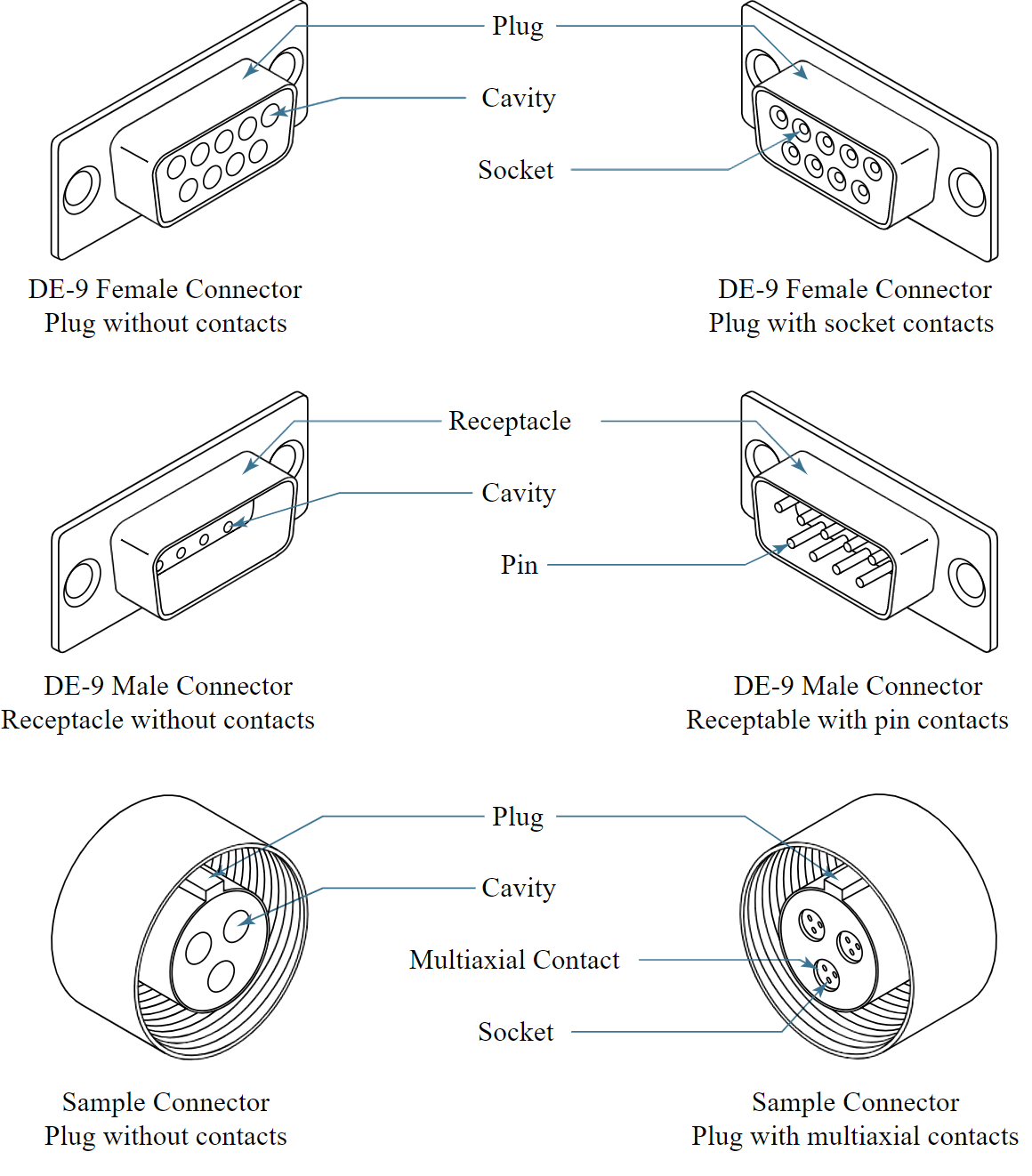
Figure 1 – Different types of connectors and parts
Sample ECAD diagrams
Figure 2 shows an excerpt of an example ECAD Diagram. In the diagram, black CAD drawings represent individual black boxes (i.e., a laptop and a network router), while the green line represents a cable.
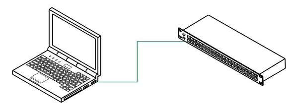
Fig 2. Example ECAD diagram
On the other hand, Figure 3 shows the schematic view of the cable used in the previous figure. Specifically, it describes how the cable represented as a green line in Figure 2—a standard Unshielded Twisted Pair (UTP) Category 5 Ethernet cable—is built.
The figure shows two connectors identified by J1 and J2. The rounded corners on their right and left sides, respectively, indicate that they are plugs. The part number for both J1 and J2 is RJ45-M (i.e., a male RJ45 plug). Both connectors have eight contacts (numbered from 1 to 8), each one attached to a conductor represented by a green line. Each conductor specifies its signal, gauge and color. Conductors are grouped in twist bundles where the conductors involved in the bundle are indicated by a line and the twist is represented by two black triangles.
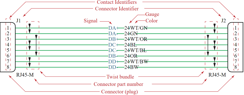
Fig 3. Example UTP category 5 Ethernet cable schematic diagram
SYSML in a nutshell
The Systems Modeling Language (SysML) is a general-purpose modeling language for systems engineering. SysML is designed to provide simple but powerful constructs for modeling a wide range of systems engineering problems. It is particularly effective in specifying requirements, structure, behavior, allocations, and constraints on system properties to support engineering analysis.
The language is intended to support multiple processes and methods such as structured, object-oriented, and others, but each methodology may impose additional constraints on how a construct or diagram kind may be used.
The official OMG SysML specification for SysML was published in September 2007. The specification was developed in response to the requirements specified in the Unified Modeling Language (UML) for Systems Engineering Request for Proposal (SE RFP) and was formally adopted by the OMG in 2006 as an extension to UML. The SysML specification is maintained and evolved by the OMG SysML Revision Task Force.
SysML versions range from 1.0 to 1.4, and several changes have been introduced since the initial publication of the standard. Version 1.0 was the first publicly available SysML specification, and was superseded by SysML version 1.1 in November 2008. Version 1.1 mostly included editorial corrections and bug fixes for OMG SysML 1.0. On the other hand, version 1.2 included important changes, such as the inclusion of UML Instances, Structured Activities, and multiple Item Flow notation; some improvements to Value Types related to Unit and QuantityKind; and a synchronization with UML 2.3 metamodel changes. Version 1.3 also included significant changes, and the machinery to specify Physical Flows was redefined: Flow Specifications were deprecated; and Nested Ports, Proxy Ports, and support for hierarchically nested Interfaces was included. Additionally, a new alignment with UML v.2.4.1 was done. Finally, OMG SysML v.1.4 only included minor (but numerous) changes to the language: references to nested Parts in composition hierarchies; Element Groups; new notations for inherited features, behavior compartments, and Port features; new model libraries; updates to the abstract and concrete syntax; etc.
The current specification defines the SysML language in three parts: (i) an abstract syntax, described by a metamodel; (ii) a concrete syntax, or notation; and (iii) the semantics of the language concepts in the systems engineering domain.
The SysML metamodel includes the concepts, features and relationships of the language. In a metamodel, the language concepts are represented by metaclasses which are related to each other using relationships such as generalizations and associations. Each metaclass has a set of features that characterize the concept it represents, and can optionally include a set of constraints. In the context of OMG specifications, metamodels are expressed in terms of the Meta Object Facility (MOF) language.
To facilitate its adoption (not only by potential users but also by modeling tools willing to support them), new languages are also typically defined as extensions of the UML language. Customization of UML-based languages is achieved by using profiles. A profile contains stereotypes, which are similar to metaclasses, and are used to extend the metaclasses in UML to create new or modified concepts in the customization. The system engineering extensions to UML in SysML are described using a profile called the SysML profile. The SysML profile can be regarded as a lightweight extension of UML that allows defining SysML models in almost any UML modeling tool, as long as the UML supports the profile mechanism. Profiles offer an intermediate solution between using a plain UML tool with no explicit support for the new language or developing a full-fledged new tool for it.
The SysML notation, or concrete syntax, describes how its concepts are visualized. In the SysML specification, this notation is described in notation tables that map language concepts to graphical symbols on diagrams. SysML includes nine diagrams as shown in the diagram taxonomy in Figure 4. In some cases, the UML diagrams are strictly reused, such as use case, sequence, state machine, and package diagrams, whereas in other cases they are modified so that they are consistent with SysML extensions. The diagrams included in SysML are the following:
REQUIREMENT DIAGRAM is a new SysML diagram type and represents text-based requirements and their relationship with other requirements, design elements, and test cases to support requirements traceability.
ACTIVITY DIAGRAM represents behavior in terms of the ordering of actions based on the availability of inputs, outputs, and control, and how the actions transform the inputs to outputs. This SysML diagram type is a modification of UML activity diagram.
SEQUENCE DIAGRAM represents behavior in terms of a sequence of messages exchanged between parts. This SysML diagram type is the same as UML sequence diagram.
STATE MACHINE DIAGRAM represents behavior of an entity in terms of its transitions between states triggered by events. This SysML diagram type is the same as UML state machine diagram.
USE CASE DIAGRAM represents functionality in terms of how a system or other entity is used by external entities (i.e., actors) to accomplish a set of goals. This SysML diagram type is the same as UML use case diagram.
BLOCK DEFINITION DIAGRAM represents structural elements called blocks, and their composition and classification. This SysML diagram type is a modification of UML class diagram.
INTERNAL BLOCK DIAGRAM represents interconnection and interfaces between the parts of a block. This diagram is used to integrate behavior and structure models with engineering analysis models such as performance, reliability, and mass property models. This SysML diagram type is a modification of UML composite structure diagram.
PARAMETRIC DIAGRAM is a new SysML diagram type and represents constraints on property values used to support engineering analysis.
PACKAGE DIAGRAM represents the organization of a model in terms of packages that contain model elements. This SysML diagram type is the same as UML package diagram.
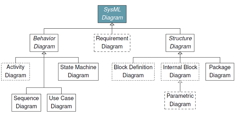
Fig 4 – SysML Diagram Taxonomy
The semantics of a language describe the meaning of its concepts in the domain of interest. Semantics are described via a mapping between the domain concepts and the language concepts. The domain concepts can be defined in natural language (e.g., English text) or more formally defined mathematically. For SysML, the domain concepts were defined by the requirements in the UML for SE RFP as English text.
SysMLe : An extension to SysML to support ECAD modeling
Strictly speaking, we could use “plain” SysML to model ECAD diagrams but the resulting models would be of very bad quality since we would need to simulate ECAD concepts using unnatural and verbose combinations of SysML blocks. With our extension, ECAD concepts become first-class elements in SysML allowing a much direct modeling of ECAD diagrams.
This section describes the extension proposal for SysML. It presents the domain model (i.e., the metamodel of the language) of the extension and a proposal for the profile extending SysML for ECAD modeling. As introduced before, profiles are the fastest way to support a new language but in exchange, they provide less control on the models specified with the profile in contrast with the option of developing a dedicated tool for the new language.
More specifically, the definition of an extension for SysML follows a process composed of three phases, namely: (i) domain model (also known as abstract syntax) definition, which covers the identification of the main concepts, features and relationships of the working domain; (ii) profile definition, which maps elements in the domain model into profile elements for SysML; and (iii) concrete syntax definition, which specifies how each profile element is represented.
SysMLe Domain model (the ECAD metamodel)
Figure 9 shows the proposed domain model defined as a metamodel, which represents the concepts as meta-classes, features as attributes and relationships as associations. This metamodel represents the abstract syntax of a Domain-Specific Language (DSL) that can be used to describe ECAD concepts.
The proposed domain model includes BlackBox and Cable metaclasses as main citizens, which allows representing black boxes (hardware components) and cables in ECAD modeling, respectively.
The BlackBox metaclass includes attributes to model both the component identifier (i.e., id) and its part number, and an association (connectors) to specify the set of connectors of the black box. Additionally, the metaclass includes an attribute to optionally model the view of the black box (i.e., the drawing to be shown in the ECAD Diagram).
The Cable metaclass includes attributes to define the cable length and part number. Cables end in one or more connectors. The metaclass also includes a composition to define the cable Bundles (which define the bundle type, see BundleType enumeration, and also has a part number). Bundles contain the set of conductors the parent cable is composed of. Additionally, the bundle metaclass includes a self-referencing association (i.e., bundles) to represent that a bundle can be composed of one or more bundles of conductors.
The Conductor metaclass represents conductors in ECAD modeling and includes attributes to model the part number, gauge, signal and color. They can be linked to a set of single contacts (contact).
The Connector metaclass represents connectors in ECAD modeling and includes attributes to model the connector identifier, its part number, its type (see ConnectorType enumeration) and, optionally, its view. The association tools allow indicating the tool used to build the contact (see Tool metaclass, which includes the part number of the tool and extra metadata). The metaclass also includes two self-referencing associations, i.e., validMates and mated, to model the set of compatible connectors for a specific connector and the connector to which the metaclass instance is attached to, respectively. Finally, the connector metaclass is composed of a set of contacts, represented by the association contacts.
The Contact metaclass represents contacts in ECAD modeling and includes attributes to model the contact identifier, its part number and the crimping setting (represented as a data map). This metaclass is abstract and the root of a hierarchy aimed at modeling the different contacts in ECAD modeling, specifically: (i) single contacts (see SingleContact metaclass), which have a type (i.e., pin or socket; see ContactType enumeration) and is connected to a conductor (see conductor association); (ii) multiaxial contacts (see MultiaxialContact metaclass), which is composed of a set of single contacts (see contacts association).
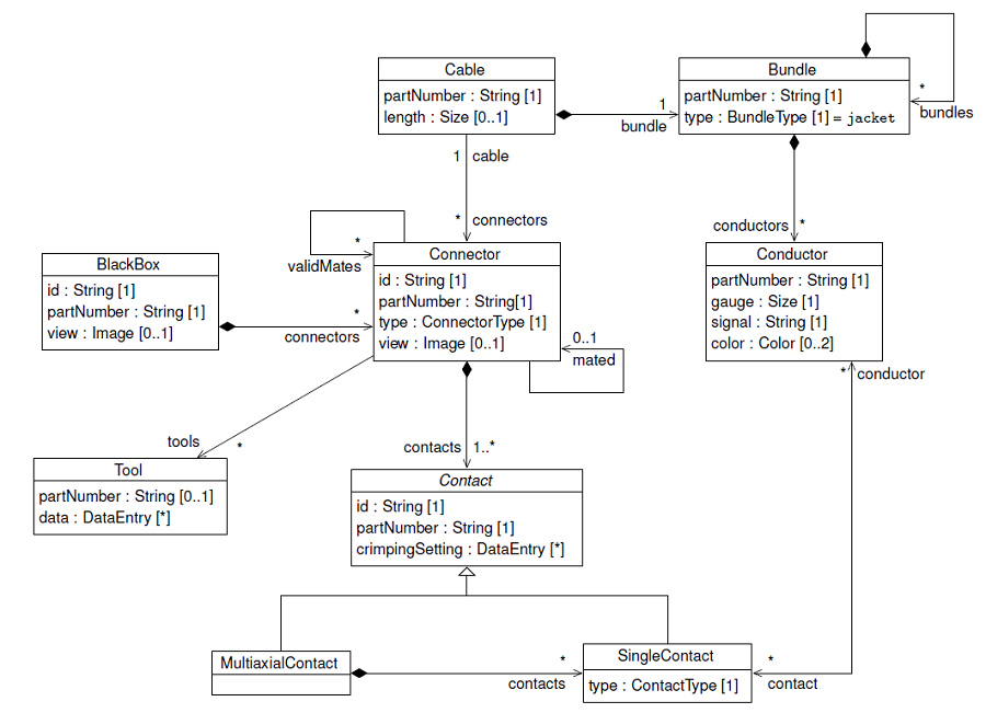
Fig 9 – ECAD metamodel
SysMLe Profile: a SysML Profile for ECAD modeling
Figure 11 offers a high-level view of the organization of the SysMLe profile. SysMLe is our proposal to extend SysML with constructs for ECAD modeling (that is what the e in SysMLe stands for).
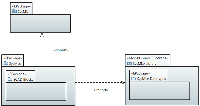
Fig 11. SysML Profile Packages for ECAD
The profile is organized into two top-level packages: (i) SysMLe Library and (ii) SysMLe. The former is a UML Model Library which defines datatypes and reusable concepts, while the latter contains the modeling concepts for the ECAD domain. These modeling concepts are UML stereotypes which extend the standard SysML stereotypes. In its current version, the SysMLe package only comprises the ECAD Blocks package.
Figure 12 shows the contents of the SysMLe Datatypes package and demonstrates how the datatypes presented in the Figure 9 have been accommodated in the profile. The translation has been almost a one-to-one mapping, however, some minor changes have been introduced: the Color enumeration has been enriched to allow arbitrary colors, and the Image datatype has been simplified looking for an alignment with the modeling tool.
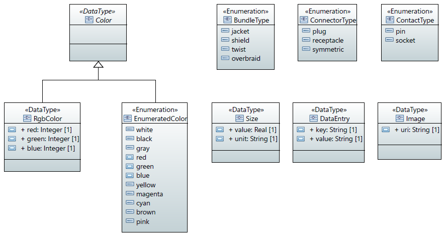
Fig 12 – SysMLe Library
On the other hand, Figure 13 shows the proposed SysMLe profile. Elements with a blue background correspond to new stereotypes introduced by the SysMLe profile, elements with a red background correspond to stereotypes imported from SysML that are extended by SysMLe, and elements with a green background correspond to metaclasses imported from the UML metamodel.
Most of the metaclasses in the domain model have been mapped to stereotypes in the profile. Attributes and associations in the domain model have been mapped either to new attributes and associations in the profile or to existing properties inherited from UML or SysML. Additionally, it is noteworthy that, in order to accommodate SysML semantics, some classes of the domain model have been split into two stereotypes (i.e., Connector and Contact). Connectors and Contacts extend FullPorts and Ports respectively, and as such (according to the UML standard), they are typed elements. Thus, ConnectorBlock and ContactBlock are the classifiers which provide the corresponding types. This organization has an additional advantage: ConnectorBlocks and ContactBlocks can be stored in model libraries that can be imported enabling reuse of pre-built elements.
According to Figure 13 then, BlackBoxes, ContactBlocks, ConnectorBlocks and Cables are the main modeling blocks. As in SysML, blocks have typed ports, that are connected via BindingConnectors. Some OCL constraints may apply, for instance: (i) ports on ContactBlocks and Cables can only be stereotyped with Connector; (ii) the type of a Connector must be a class annotated with ConnectorBlock; and (iii) the type of Contact ports must be a ContactBlock. Conductors are represented as BindingConnectors. Since Conductors are UML Connectors, they represent a link between properties. In SysMLe, specifically, Conductors are restricted to connect ports stereotyped as Contacts.
Some concepts, however, have been transformed into properties since they do not correspond to objects that are going to be depicted in the diagram, but that contain additional information which is attached to elements shown in ECAD Diagrams. This is the case of the Tool, which has been included as the toolInfo property in the ConnectorBlock stereotype. Other properties have been omitted since they can be represented using the properties inherited from UML. This is the case for the cables self-association of the Cable class in Figure 9. Since the stereotype Cable extends UML Class, it can contain nested classifiers. Thus, the self-association is not needed in the SysMLe Cable stereotype.
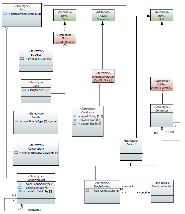
Fig 13. SysMLe Profile
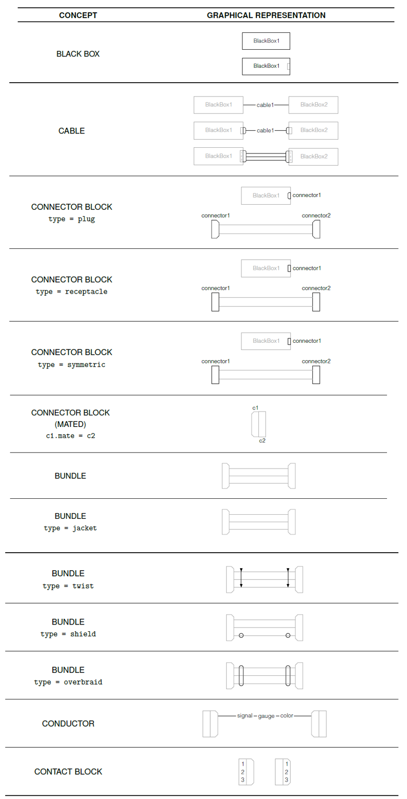
A concrete syntax for SysMLe
SysMLe profile elements are employed in a new kind of diagram called ECAD Diagram, which extends both the Block Diagram and Internal Block Diagram from SysML.
Table 14 describes the graphical representation of each SysMLe profile element in the ECAD Diagrams. The proposed concrete syntax is based on the common notation used in ECAD modeling tools. For the sake of clarity, the graphical representation of each element is shown in black while other contextual elements may be added in gray. Only profile elements with concrete syntax are shown.
We have also “formalized” the description of the profile following the typical structure used in OMG documents but we skip it here since the goal of the post is to give an overview of our ideas. Feel free to get in touch for more details. The profile has been implemented in Papyrus but only the profile definition, not the editor to be able to use that profile with our proposed concrete syntax.
FNR Pearl Chair. Head of the Software Engineering RDI Unit at LIST. Affiliate Professor at University of Luxembourg. More about me.

Great job, Jordi and team! I look forward to seeing what we can do with this, and what capabilities we can put in the hands of users.
Hello, are you aware of the MARTE HRM profile ? why not propose an evolution of this standard ? building your own SySML extension is a good job but does not make your extension a standard. however, proposing the same design language as part of MARTE will make it an OMG standard.
Dear Asma, yes, we are aware of the MARTE HRM profile, but we considered more natural to extend SysML rather than extending MARTE. We think that the SysML concepts of Ports, Blocks and Connectors better represent the structural concepts of a Cable/Connector we need for SysMLe. Also keep in mind that one important part of our proposal is not only the extension of the abstract syntax of the standard, but also of the concrete syntax. In this case, I’m afraid that from the standandardization point of view, both solutions are the same: both SysML and MARTE are OMG standards, none of them provide the exact concepts we want to model (so we need to extend the abstract syntax), and none of them provide a suitable concrete syntax. So in any case, we need to introduce non-standard concepts to an OMG standard. Finally, we think that SysML was a better choice because we think it is closer to our purpose: the modeling part of MARTE is mostly supposed to give support to the analysis of real time/embedded systems; but in SysMLe, we are not so interested in such analysis, but we just want to model the structural part of cables. Thanks anyway for your suggestion!
Hello, How are the other elements of SysML accomodated? Specifically, can the data generated in the modeling effort be captured in SysML data tables? Can custom table quires be built with meta-chains operating on the data contained from the new SysMLe elements? Features such as these will truly “embed” the concept within SysML and make it infinity more useful.
Hello Tim. I agree that there are many other possibilities and extensions that could make this even more useful, but what you see is all we did. This was an exploratory work that didn’t go further.
Is it possible to get the profile you have for experimintation
The post includes the profile definition but I’m afraid we’re not allowed to publicly share the profile itself.
Team, great concept. The MBSE value chain is broken with the handoff of SySML drawings done by our SEs and the rework into wiring diagrams to build harnesses by our EEs. A SysML extension to unify the tooling used in house or to allow for better integration of existing products would be awesome. Has there been any recent feedback from OMG on this research project?
Dear Chris. No, no feedback but we never took any specific action to show this to the OMG as this was part of tech transfer project for a specific company