
Water scarcity has been and will continue to be a global-scale environmental issue [1]. This concern has motivated strategies and solutions for water reuse/recycling to treat and recover water from various sources for beneficial purposes such as agriculture, water supply, groundwater replenishment, industrial processes, and environmental restoration.
Wastewater treatment plants (WWTPs) are one of the solutions for cleaning wastewater (urban or industrial) so that it can be safely returned to the environment. Various physicochemical and biological processes and treatments must be performed on the wastewater to remove contaminants and suspended solids, break down organic matter, and disinfect the liquid. Currently, WWTPs use Cyber-Physical Systems (CPSs) and the Internet of Things (IoT) to monitor, control, and automate different processes in the plant. Devices such as sensors (e.g., level, temperature, or pH sensors), and actuators (e.g., motors, valves, or alarms) are deployed in different water treatment processes to collect real-time data and control operations. Additionally, multi-layer IoT systems that leverage edge and fog computing also deploy nodes or compute units (located in the plant) to run lightweight applications and databases that store some of the collected information. Finally, some cloud servers are also provisioned for the deployment and execution of the resource-intensive applications, such as AI algorithms.
Although several operating units (such as biological reactors, decanters, thickeners, etc.) are involved in wastewater treatment, the whole plant should be considered as an integrated process to study improvements in processes such as sludge control, primary sedimentation effects, and energy and nutrient recovery [2]. Therefore, WWTPs are represented by a single process block diagram that illustrates the treatments, stations, operation units, and flow of water and sludge.
There are several ways to design the process block diagrams using multiple concepts, shapes, connectors, and notations such as those used in the diagrams designed by [3,4]. However, there is a need for a unified language for modeling WWTP process block diagrams, including the IoT system integrated in the different wastewater treatment stages. Therefore, we propose a modeling-based solution consisting of:
- a domain-specific language (DSL) to model the process block diagram of a WWTP including the IoT system involved in the wastewater treatment stages;
- a code generator that produces the code for the deployment and execution of the IoT system; and
- a MAPE-K based framework to self-adapt the system and control devices at runtime.
This work is part of the European TRANSACT project, whose goal is to develop a distributed solution architecture for the transformation of safety-critical cyber-physical systems, from localized standalone systems into safe and secure distributed solutions leveraging edge and cloud computing.
DSL for Waste Water Treatment Plants
Models are built using DSLs, which provide a set of abstractions and vocabulary closer to that already used by domain experts, facilitating the modeling of new systems for that domain. Our DSL address the specification of WWTPs process block diagrams including the IoT systems involved in the different wastewater treatment stages. This DSL is an extension to the language for modeling self-adaptive IoT systems that we discussed in this post.
Specifically, this DSL version enables the modeling of:
- WWTP process block diagram: we enable the specification of the main operating units such as Filtrators, Grist Chambers, Biological Reactors, and the flow (either water or sludge) between these operating units.
- IoT system: this DSL enables the modeling of the IoT system (infrastructure and container-based software), including sensors, actuators, nodes (edge, fog, and cloud), physical regions, applications, and other main concepts of the system.
- Adaptation and functional rules: the modeling of functional rules to cover functional requirements (e.g., triggering alarms upon detection of unusual states) and adaptation rules for self-adaptation of the IoT system (e.g., recovery from failures) are also addressed by this DSL.
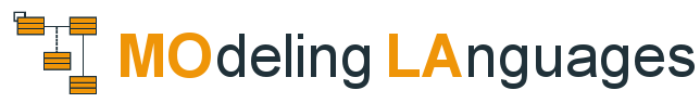
Figure 1 shows an excerpt of the metamodel (abstract syntax) with the relevant concepts for the specification of the process block diagram and the IoT system (you can found the entire metamodel in the project repository). Concepts that inherit from OperationUnit represent a sector of the plant that performs either water or sludge treatments such as Decanter, GristCahmber, or Filtrator. The Flow concept represents the inflows and outflows (either sludge or water) to each OperationUnit. An OperationUnit can have several inflows and outflows represented by the relationships from and to. The relationship region specifies the region or area in which the OperationUnit is physically located on the plant, and the relationship devices allows specifying the IoT devices, either sensors or actuators, deployed in each OperationUnit.
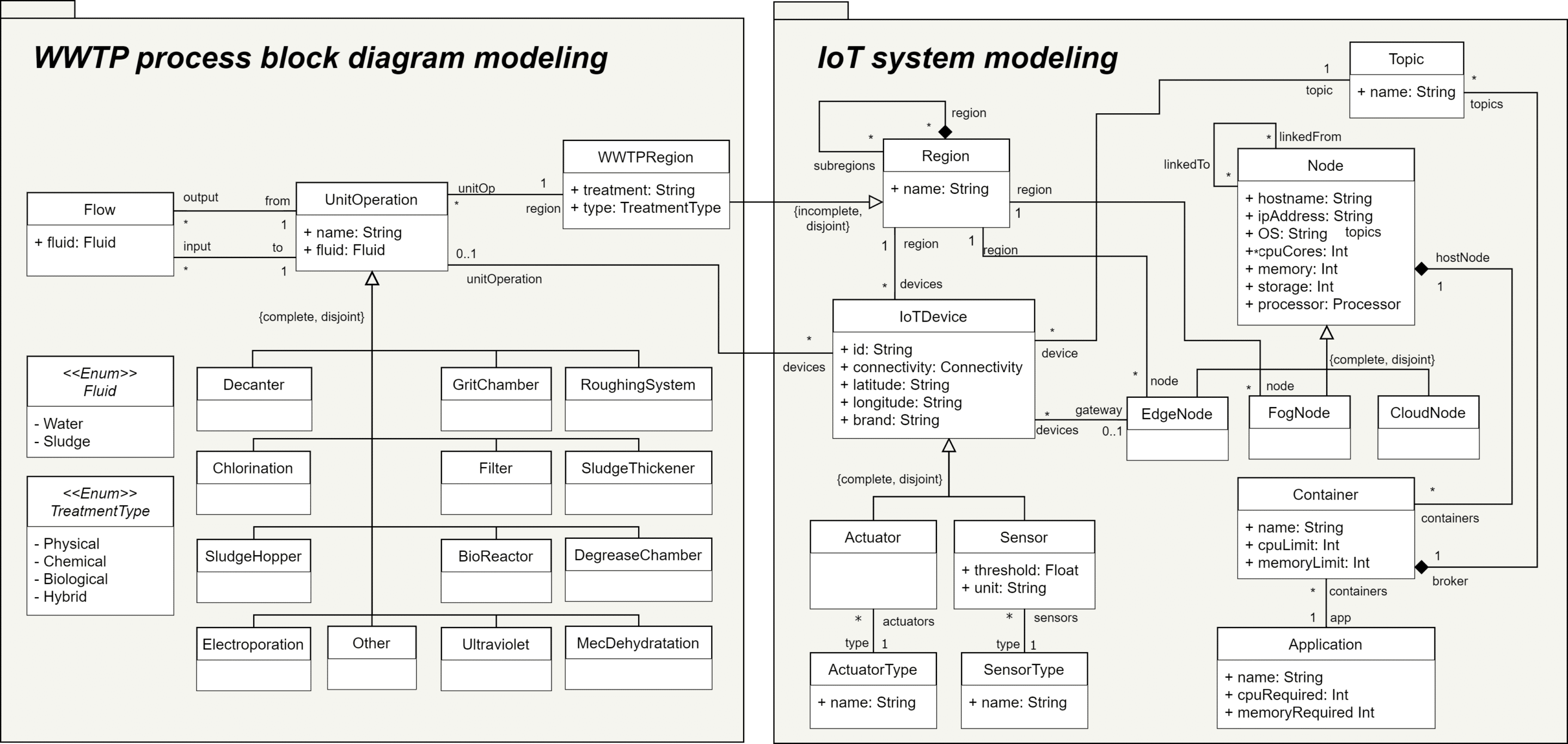
Figure 1. Metamodel
Figure 2 shows the process block diagram (modeled using our DSL) for the Algemesí WWTP, a plant located in Valencia, Spain. This WWTP has five operating units in the water treatment line (blue shapes) and three operating units in the sludge treatment line (yellow shapes). The operating units can be instantiated by dragging and dropping the shape from the Diagram Palette located on the right side. Water or sludge flows can be created selecting the fluid type from the source operating unit and connecting the target operating unit.

Figure 2. WWTP process block diagram
The list of sensors and actuators must be specified for each operating unit. Figure 3 shows an example list of devices deployed on the GC-01 Grit Chamber: four sensors (pH, electrical conductivity, total suspended solids, and level) and two actuators (valve and buzzer) are modeled for this example. All IoTDevices have a type, a brand, a connectivity type (such as ethernet, wifi, ZigBee, or another), and their geographic coordinates. We also cover the concepts for specifying publish/subscribe communication between IoT devices and nodes. Sensors will be publishers in topics while actuators will be subscribers. Finally, unit and threshold parameters are configurable only for devices that collect information (i.e., sensors). The threshold parameter represents a limit value that could later be used to define functional or adaptive rules. For example, turning on an alarm if the threshold of the level sensor is exceeded.

Figure 3. List of sensors and actuators
The modeling of other concepts such as the plant regions, the nodes (edge, fog, y cloud) and containers within are depicted using textual, tree-based and tabular notations. More examples of modeling these concepts can be consulted in our paper A model-based infrastructure for the specification and runtime execution of self-adaptive IoT architectures co-authored by Iván Alfonso, Kelly Garcés, Harold Castro and Jordi Cabot (paper accepted and soon to be published in the Computing Journal).
Regarding the modeling of rules, we have categorized them into two groups: (1) functional rules to implement the functional system requirements and (2) adaptation rules to guarantee QoS constraints. Each rule consists of a condition and one or more actions that would be executed if the condition becomes true during a certain period.
Figure 4 shows two rules modeled. One functional rule (GC-level Alarm) states that if the GC-level sensor detects a value greater than 400 cm for 5 minutes, then open the GC-valve and turn on the GC-alarm. The second rule (High CPU consumption) checks if the CPU consumption of the edge-01 node exceeds 80% for 60 seconds, then the realtime_app container (assuming this container is hosted by the node) will be offloaded to the edge-02 node to free up workload on the edge-01 node and prevent it from failing.
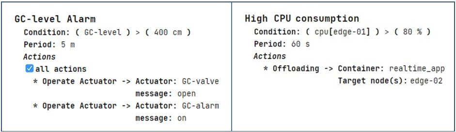
Figure 4. Example rules
Tool support
Our DSL is implemented using MPS (Meta Programming System), an open-source language workbench developed by JetBrains. Projectional editors such as MPS enable editing of the model by means of projections of the abstract syntax, but the model is stored in a format (e.g. XML) independent of its concrete syntax. In other words, the user interacts with these projections, which are then translated by the editor to modify the persisted model. Some benefits of projectional editing are discussed below (Völter, 2011).
- No grammar or parser is required.
- Graphical, semi-graphical, and textual notation can be combined.
- The IDE used for model editing can provide code completion, error checking and syntax highlighting.
- It is possible to provide several representations (projections) for the same model, since the model is stored independently of the concrete syntax.
Defining a language in MPS involves the design of several aspects. The definition of our DSL includes six aspects: Structure to define the language concepts (abstract syntax), Editor to define the editors for those concepts (concrete syntax), Constraints and Type-System to define a set of time-system rules and constraints (well-formedness rules), Behaviour to define reusable methods and functions, and Generator to define a code generator.
Code generation and run-time execution
Figure 5 summarizes an operational view of our architecture by distinguishing design time (left-hand side) and runtime (right-hand side). In the runtime stage, the operation and self-adaptation of the IoT system is performed. To achieve this, we have designed the architecture based on the MAPE-K loop, which has been widely employed for the design of self-adaptive systems. The four stages of the MAPE-K loop enable the Monitoring or collection of information on the current state of the system, the Analysis of the collected information, the Planning of the list of actions or adaptations to be performed on the system, and the Execution of the adaptation plan.
Our approach leverages different technologies and tools for each stage of the MAPE-K loop. For example, we use Prometheus and several of its modules (such as Alerting Rules and Alert Manager) to store the information, analyze it, and detect when an adaptation should be applied to the system. We have also built the Adaptation Engine to execute the actions and adaptations on the IoT system through the orchestrator (K3S or Kubernetes). The code for the deployment and configuration of these technologies required for the system execution is produced by the Code Generator, which takes as input the model designed by the user using the DSL.

Figure 5. Solution overview
The collected metrics (sensor, infrastructure, and QoS data) can be queried in real time by the user using the Prometheus graphical user interface. For example, Figure 6 shows a list of rules previously configured by the user, including their current status (Inactive, Pending, or Firing). In addition, our Code Generator also produces the code for the deployment and configuration of Grafana, an open-source data visualization tool to enables the design and customization of dashboards. Grafana is compatible with several sources and databases (such as Prometheus time-series database) enabling a more comprehensive data display alternative.
Figure 6. List of rules – Prometheus user interface
Summary
Towards unifying a language for modeling the WWTP process block diagram and managinig the IoT system to monitor and control different aspects during watewater treatment, we propose a modeling-based solution that involves the design of a DSL for modeling the WWTP diagram and the IoT system, a code generator to produce the system deployment and configuration code, and a MAPE-K based framework to operate and manage the system at runtime.
References
[1] Brusseau, M. L., Ramirez-Andreotta, M., Pepper, I. L., & Maximillian, J. (2019). Environmental impacts on human health and well-being. In Environmental and pollution science (pp. 477-499). Academic Press.
[2] Jeppsson, U., Alex, J., Batstone, D. J., Benedetti, L., Comas, J., Copp, J. B., … & Vrecko, D. (2013). Benchmark simulation models, quo vadis?. Water Science and Technology, 68(1), 1-15.
[3] Solís, B., Guisasola, A., Flores-Alsina, X., Jeppsson, U., & Baeza, J. A. (2022). A plant-wide model describing GHG emissions and nutrient recovery options for water resource recovery facilities. Water research, 215, 118223.
[4] Solon, K., Flores-Alsina, X., Mbamba, C. K., Ikumi, D., Volcke, E. I. P., Vaneeckhaute, C., … & Jeppsson, U. (2017). Plant-wide modelling of phosphorus transformations in wastewater treatment systems: Impacts of control and operational strategies. Water Research, 113, 97-110.
[5] Völter, M. (2011). Language and IDE modularization, extension and composition with MPS. Pre-proceedings of Summer School on Generative and Transformational Techniques in Software Engineering (GTTSE), 395-431.


very interesting
Thanks Zahra!
Very nice case on combining different views and notations. Related to the metamodel (language definition) how you handle in the DSL that correct sensor inputs or actuator operations are applied? Or is the idea that modeler can use any based on publish/subscribe?
Thank you for your comment. Regarding asynchronous communication, the user must to specify the messaging broker including the topics that will be used. Subsequently, these topics are associated to each device (sensor or actuator). In this way, we ensure that the information published in the (sensor) topics is collected and analyzed at runtime, and that the control commands for an actuator are published in the corresponding topic. The complete metamodel (including the concepts defined for asynchronous communication) can be found in the project repository.
https://github.com/SOM-Research/WWTP-DSL
Thank you for the reply which I understood that it is left to the user yet publish/subscribe ensures possible commands.
As an example, and trying to use the case from the article, the approach ensures that ‘start’ command can be sent to Roughing System (RS-01), but not that it should not be sent in case the system is empty?
That’s right, our system ensures that the control commands are sent to the actuators (i.e. to the topics). Following the example, if the ‘GC-level Alarm’ rule is fired, then the ‘open’ and ‘on’ messages will be sent to the ‘wwtp/valve’ and ‘wwtp/buzzer’ topics respectively. The user must ensure that the actuators are actually subscribed to these topics, and that they are able to process the control command. We have discussed ways to improve consistency in these communications and one of the strategies could be the implementation of AsyncAPI (as part of future work).
Good work! I would suggest to use semantic link types for certain associations such as the one between OperationalU.nits and IOT-Devices. Here, the link type could be “signalconnection”
Yes, good work indeed. Adding my 25 cents, I would recommend to not inherit the OperationUnit class into subclasses based on their subtype. Instead relate OperationUnit to a specification class (e.g. OperationUnitType) that specifies the type of OperationUnit. That way, you have a configurable model instead of a hard-coded one. But, again, good work!
Best
Nils
Manfred, Nils, thanks for the suggestions. We have updated our metamodel to the latest version.
Using a specification class (e.g. OperationUnitType) is a good alternative in this case. However, we had defined the inheritance of OperationUnit since we were thinking in the future to extend the metamodel to add properties and attributes specific to each OperationUnit. For example, for the Biological Reactor enable the specification and description of the oxidation phases (anaerobic and aerobic), or the oxygen requirements to ensure proper operation.