
Traditional IoT systems rely on cloud-based architectures, which allocate all processing and storage capabilities to cloud servers. Although cloud-based IoT architectures have advantages such as reduced maintenance costs and application development efforts, they also have limitations in bandwidth and communication delays [1]. These limitations are intended to be addressed with edge and fog computing, whose objective is to distribute processing and storage close to data sources (i.e. things). Today, developers tend to leverage the advantages of edge, fog, and cloud computing to design multi-layered architectures for IoT systems.
Nevertheless, creating such complex designs is a challenging task. Even more challenging is managing and adapting IoT systems at runtime to ensure the optimal performance of the system while facing changes in the environmental conditions. Indeed, IoT systems are commonly exposed to changing environments that induce unexpected events at runtime (such as unstable signal strength, latency growth, and software failures) that can impact its Quality of Service (QoS). To deal with such events, a number of runtime adaptation rules should be automatically applied, e.g. architectural adaptations such as auto-scaling and offloading tasks.
In this sense, better support to define and execute complex IoT systems and their (self)adaptation rules to semi-automate the deployment and evolution process is necessary. In our paper A model-based infrastructure for the specification and runtime execution of self-adaptive IoT architectures (open access), co-authored by Iván Alfonso, Kelly Garcés, Harold Castro and Jordi Cabot, published in the Computing Journal, we introduce our research which aims to overcome these concerns by presenting a model-based infrastructure for the specification and runtime execution of multi-layered IoT architectures, including self-adaptation rules. Our proposal combines a DSL for the specification of static and dynamic aspects of this type of systems together with a runtime infrastructure and a code-generator able to semi-automate their deployment and runtime monitoring and adaptation.
This work is an extension of our previous study Modeling self-adaptive IoT architectures, in which we proposed a first version of a DSL for IoT systems and a proof of concept of a code generator. The current work extends this previous contribution to the following aspects:
- Metamodel improvement: we have enhanced the metamodel to support modeling new DSL concepts such as sensor threshold values, publish/subscribe messaging, and data persistence for containers.
- Runtime support: we have developed a framework based on the MAPE-K [2] loop to automatically monitor, execute the expected behavior and self-adapt the IoT system.
- Code generator enhancements: We now generate the code required to support the execution of the whole system at runtime.
- a DSL extension for the mining industry: we propose an extension of our DSL focused on the modeling and operation of IoT systems in the underground mining industry.
- Empirical evaluations: we have designed and conducted empirical experiments to validate the expressiveness and usability of our DSL and the correctness of the generated code.
Approach overview
Fig. 1 summarizes an operational view of our architecture by distinguishing design time (left-hand side) and runtime (right-hand side). At design time, the user creates an initial IoT system specification model using the modeling editor for the DSL described in the following sections. The code generator transforms such a specification into a set of deployment and configuration options that describe a MAPE-K loop which is performed at runtime. The four stages of the MAPE-K loop enable the Monitoring or collection of information on the current state of the system, the Analysis of the collected information, the Planning of the list of actions or adaptations to be performed on the system, and the Execution of the adaptation plan.

Figure 1. Approach overview
Running example
We will use a Smart Building scenario as a running example to illustrate our approach. For the purposes of our example, let’s assume that a hotel company (Hotel Beach) wants to reduce fire risks by automating disaster management in its hotels. A fire alarm and monitoring system are implemented in each of the company’s hotels. We will assume that all buildings (hotels) have three floors with two rooms each. Fig. 2 presents an overview of the 1st floor. Based on this, the infrastructure (device, edge, and cloud layers) of the company hotel IoT system would be as follows:
- Device layer: each room has a temperature sensor, a carbon monoxide (CO) gas sensor, and a fire water valve. Furthermore, an alarm is deployed on the lobby. Each sensor has a threshold measurement to activate the corresponding alarm, e.g., a person should not be continuously exposed to CO gas level of 50 parts per million (ppm) for more than 8 hours.
- Edge layer: in each room, an edge node receives the information collected by the sensors of the device layer and run a software container (C1 and C2) for analyzing sensor data in real time to check for the presence of smoke and generate an alarm state that activates the actuators. A fog node (linked to the edge nodes), located in this same floor, runs the C3 container (running App2, a machine learning model to predict fires), and C4 (running App3, in charge of receiving and distributing data, typically a Message Queuing Telemetry Transport (MQTT).
- Cloud layer: the cloud layer has a cloud server node that runs the C5 container, a web application (App4) to display historical information of sensor data and of fire incidents in any of the hotel’s property of the company.
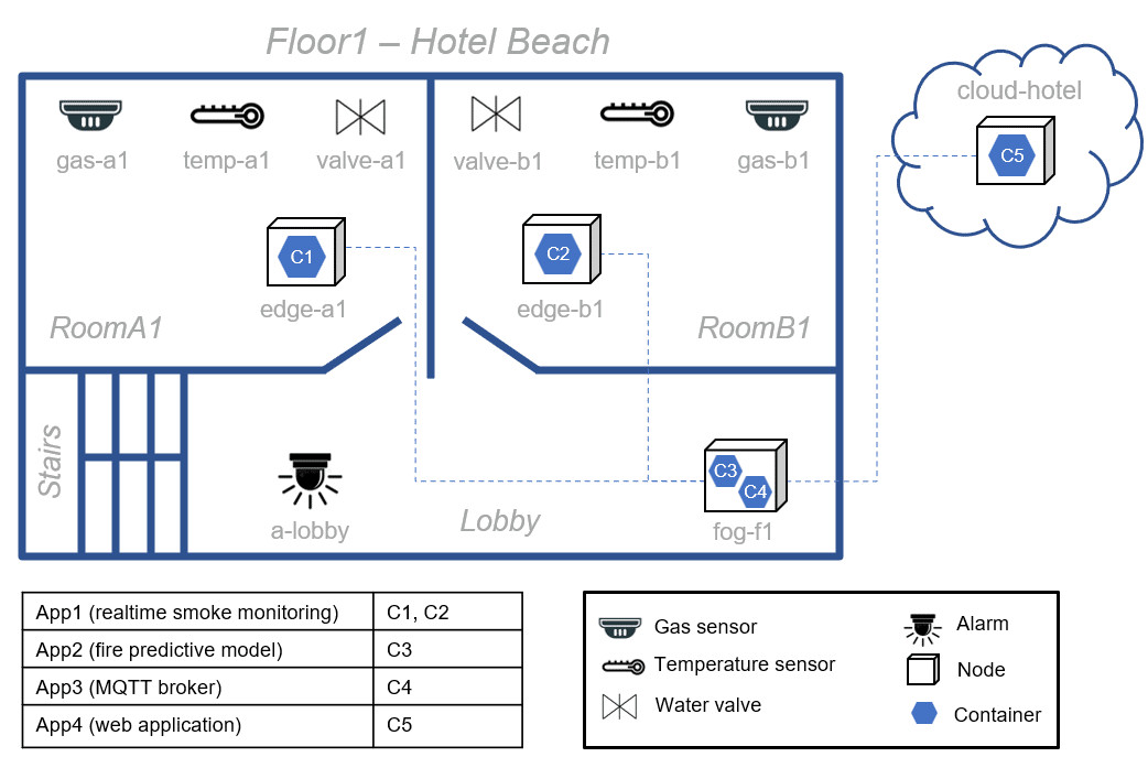
Figure 2. Smart building IoT system
This covers the static view of the system, but the dynamic aspects that threaten the operation of IoT systems must also be addressed. For instance, a flooding could cause failures in the edge-a1 node; then it will be necessary to migrate the C1 container to another suitable node to ensure the continuous monitoring of the smoke presence. Our research addresses this type of architectural adaptations by proposing a rule-based language for the runtime execution of IoT systems that can also be used to address their functional requirements.
DSL for the specification of multi-layered IoT systems
Our DSL has two main components, the sublanguage to describe the IoT architecture and the sublanguage to describe the rules governing the self-adaptation to this architecture to adapt to changes in the environment the IoT system lives in.
Modeling the IoT architecture
Fig. 3 shows the metamodel that abstracts the concepts to define multi-layer IoT architectures. The concepts for representing the IoT system infrastructure and the deployment of container-based applications have been captured in this metamodel. While the IoTDevice concept enables the modeling of sensors and actuators (device layer), the Node concept allows modeling nodes from the edge, fog, and cloud layers. Physical (or even virtual) spaces such as rooms, stairs, buildings, or tunnels can be represented by the concept Region.
A Node can host several software containers according to its capabilities and resources (primarily cpuCores, memory, and storage). Each Container runs an Application and can have Volumes (a mechanism for persisting data used and generated by containers). Also, the specification of asynchronous communications is covered (by defining Topics).
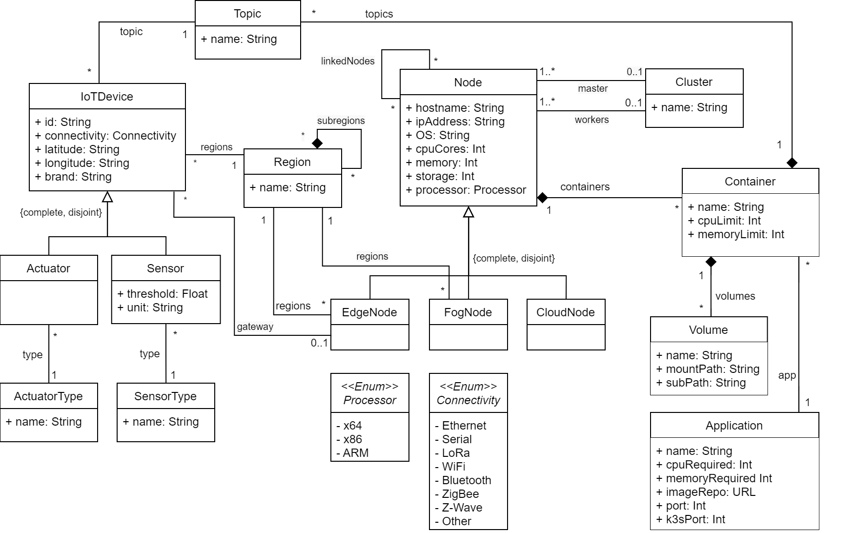
Figure 3. Multi-layer IoT architecture metamodel
Together with the abstract syntax (metamodel), each language should provide one or more concrete syntaxes. A concrete syntax refers to the type of notation (such as textual, graphical, tabular, or hybrid) to represent the concepts of the metamodel. We take advantage of MPS projectional editors to define a hybrid notation (textual, tabular, and tree view). Projectional editors are editors in which the user’s editing actions directly change the Abstract Syntax Tree (AST) without using a parser. Our DSL enables the modeling of all concepts using a textual notation. Additionally, for some concepts we also offer complementary notations that we believe are better suited for that concept. For example, Fig. 4 shows a tabular notation with the list of sensors and actuators located in the RoomA1 region.
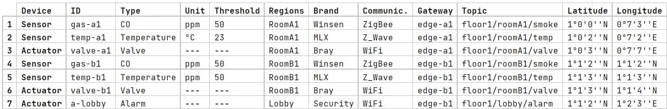
Figure 4. Modeling example of sensors and actutators (tabular notation)
Modeling the self-adaptation rules
The dynamic environment of an IoT system requires dealing with expected and unexpected events. The former may trigger actions to comply with the standard behavior of the system (e.g., to turn on an alarm upon detection of fire), unexpected ones may require a self-adaptation of the system itself to continue its normal operation. Fig. 5 presents the metamodel of our rule-based language that can cover both types of events (and even mix them in a single rule).
Every rule is an instance of Rule, which is composed of a condition (Expression concept) and multiple Actions that are executed on the system if the condition is true during a defined period. Two types of conditions can be specified: (1) SensorCondition represents the occurrence of an event resulting from the analysis of sensor data (e.g., the detection of dioxide carbon gas by the gas-a1 sensor), and (2) QoSCondition is a relational expression that represents a threshold of resource consumption or QoS metrics (e.g., to detect when the CPU consumption of a node exceeds 90%).
An action can be classified as Offloading, Redeploy, Scaling, or OperateActuator:
- The Offloading action consists in migrating a container from a source node to a destination node. This migration can be between nodes of different layers.
- The Scaling action involves deploying replicas of an application (the number of replicas to be deployed is defined by the instances attribute).
- The Redeployment action consists in stopping and redeploying a container running on a node.
- Finally, the OperateActuator action is to control the actuators of the system (e.g., to activate or deactivate an alarm). The message attribute represents the control command that will be published in the broker and interpreted by the actuator.

Figure 5. IoT system dynamic rules metamodel
As an example of an adaptive rule, we model the rule shown in Figure 6 to guarantee the execution of the C4 container deployed on the fog-f1 node of the IoT system (running example). This rule offloads the container C4 hosted on node fog-f1 to a nearby node (e.g., node edge-b1) when the CPU consumption exceeds 80% for one minute. If the edge-b1 node does not have the necessary resources to host that new container (when the rule is activated), a Region (e.g., Floor1) can be specified so that a suitable node will be searched there. However, if this offloading action cannot be executed, for example, because in Floor1 there is no node capable of hosting the container, then we must define a backup action. Therefore, we have modeled a second action (Scaling) to deploy a new container instance of the App3 application on any of the nodes of the Hotel Beach. When a list of actions is specified, the checkbox all actions controls whether all or only a certain number of them should be performed. All actions in the list will be performed. For this modeled rule, only one action (the first one, or the second one if the first one fails) will be executed.
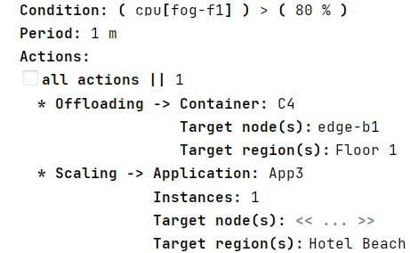
Figure 6. Example of a rule modeled with our DSL.
DSL extension: coal underground mining
Our DSL can be used as is to model any type of multi-layered IoT system. However, it has also been designed to be easily extensible to further tailor it to specific types of IoT systems. As an example, we present an extension of our DSL to model underground mining systems.
Our extension of the DSL for the mining industry addresses the modeling of subway coal mine structure, as well as additional notation for its specification. You can find more details of this extension in our paper and in the extended DSL for mining repository.
DSL tool Support
Our DSL is created using MPS, an open-source language workbench developed by JetBrains. By building the DSL on top of MPS, we could design projectional editors for the DSL with facilities for the implementation of the different notations highlighted in the previous sections. The DSL editor is freely available in our repository.
Runtime tool support
Based on the MAPE-K loop, our runtime architecture is composed of a set of components and technologies to monitor, analyze, plan, and execute adaptations as illustrated in the right-hand of Fig. 1.
In the Monitor stage, the collected information is stored in a Prometheus time-series database. This information is classified into two groups: (1) infrastructure and QoS metrics, and (2) information that is published in the system’s MQTT broker topics such as temperature, humidity, gas levels, and other types of sensor data. In the Analyze stage, we use Prometheus Alerting Rules to detect firing alerts and send notifications to next stage. In the Plan stage, an adaptation plan with the appropriate actions to adapt the system is prepared and sent to the Adaptation Engine. This engine (in the Execute stage) applies each of the actions according to the adaptation plan.
Code generator
To configure and run the runtime infrastructure of an IoT system from its DSL model, we have implemented a model-to-text transformation that generates YAML files to deploy the IoT system’s container-based applications and the components of each stage of our MAPE-K loop-based framework, including its internal logic. The generated code includes YAML deployment/configuration files for the container-based IoT applications (following the running example, the YAML manifests for deployment of containers C1, C2, C3, C4, and C5), the monitoring tools and exporters (such as kube-state-metrics and node-exporter), the Prometheus platform (Storage, Alerting Rules, and Alert Manager components), the Adaptation Engine, and the Grafana application to display the monitored data stored in the Prometheus database. You can access a code generated for the running example here.
Empirical Evaluation
We conducted two experiments to validate the expressiveness and ease of use of our DSL extended for mining industry: experiment 1, focused on specific mining concepts, and experiment 2, focused on core architectural concepts, both based on the basic methodology for conducting usability studies [3]. Both also cover the modeling of adaptation rules. A total of eight participants with knowledge of the mining domain were involved in experiment 1, and five researchers and computer science students were involved in experiment 2. The designs of the experiments and the results are reported in our paper.
Additionally, to evaluate the self-adaptation capability of our approach and the correctness of the code-generation and runtime infrastructure, we conducted experiments testing the architectural adaptations (scaling, offloading, and redeployment).
Summary
We have presented a model-based approach for the specification and runtime execution of multi-layered architectures of IoT systems and their self-adaptation rules. Our approach comprises a new DSL to model such systems, a code generator, and a runtime infrastructure, based on the MAPE-K loop, to monitor and execute the IoT system at runtime based on a variety of rules, involving architectural adaptations and rules to address functional requirements.
You can check the slides of the presentation in the SAM’21 conference about the first version of our DSL
References
[1] Jiang, Z. Huang, and D. H. Tsang, “Challenges and solutions in fog computing orchestration,” IEEE Network, vol. 32, no. 3, pp. 122–129, 2017.
[2] Kephart JO, Chess DM (2003) The vision of autonomic computing. Computer 36(1):41–50
[3] Rubin J, Chisnell D (2008) Handbook of usability testing: how to plan design and conduct effective tests. John Wiley & Sons, New Jersey
Featured image created with freepik


Congratulations!
The paper Modeling self-adaptative IoT architectures will help me elaborating on a Research Project involving Fog/Edge Computing and ML.
Thanks.
hey, this is nice work, i am very interested in your developments on this, keep going
Hello,
Please, leave your contact.
When I formalize the Project, I will send it to you.
Best Regards.
Luiz Camargo
[email protected]