In Model-Driven Engineering (MDE), models are often expressed following a graphical representation of their concepts and associations. MDE tooling allows developers to create models according to their graphical syntax and subsequently, generate code or other kind of models from them. However, the development of full-fledge graphical modeling tools is a challenging and complex task [18]. These tools usually address specific languages and platforms, as supporting multiple ones is not a viable option given the implementation and integration costs.
Although the advantages of following the path defined by Language Server Protocol (LSP) are clear for IDE development aimed at graphical languages, currently the question about how to do it properly remains open as LSP has been defined without considering graphical languages. Basically, there is no scientific assessment or tool provider position on whether LSP provides enough expressiveness for graphical manipulations, whether it should be extended to support specific features of graphical edition or whether it would be best to ignore LSP in graphical modeling. Furthermore, LSP definition is still an ongoing work, thus it could be the right moment to suggest reasonable adaptations or extensions to provide support for graphical languages.
In this work we present our vision to decouple graphical language IDEs, to this aim we (1) study the alternatives of LSP usage and their pros and cons, so practitioners may have a comprehensive view of the possible paths to follow; and (2) we propose a realization based on a specific approach leveraging LSP to handle the communication between a language-agnostic graphical client tool and a graphical language-specific server.
This work will be presented at theACM/IEEE 21st International Conference on Model Driven Engineering Languages and Systems (MODELS 2018).
Contents
Background
We present a brief description of graphical modeling languages, their editors and the Language Server Protocol (LSP).
Graphical Modeling Languages
A modeling language is defined by three main components [9]: abstract syntax, concrete syntax, and semantics. We call graphical modeling languages to those languages that define a concrete syntax relying on graphical elements (i.e., symbols like figures or pictures). A graphical concrete syntax definition includes three elements [1]: (1) graphical symbols (e.g., lines, areas or figures), including the labels for representing textual information (e.g., the names of modeling elements), (2) compositional rules, which define how these graphical symbols are nested and/or combined (e.g., an element contained in another), and (3) mapping of the graphical symbols to the elements of the abstract syntax (e.g., a specific model element type is visualized by a rectangle).
Instances of graphical modeling languages are created by means of the corresponding editor, which follows the compositional rules and the mapping information to create instances of the abstract and concrete syntaxes of the language. The next subsection will describe the main features of this kind of editors.
Graphical Modeling Editors
The development of editors for graphical modeling languages is usually more complex and challenging than for textual modeling languages. Unlike text documents, which are composed of sequences of characters; graphical modeling languages can be considered graphs where nodes and edges have a specific concrete syntax.
The atomic unit in a textual language is the character, and edit actions are expressed in terms of ranges of characters; while in graphical languages the atomic operation units are nodes and edges, and thus editing actions affect them. Additionally, text documents are usually processed from top to bottom and from left to right, thus meaning an implicit ordering (relevant for features such as scoping or links). In graphical languages, elements may be freely arranged in a canvas and (processing) order must be explicitly stated by means of establishing relationships among nodes.
Regarding the serialization support, while text editors just read, display and write raw text, graphical editors usually display a graphical representation of a model (e.g., a canvas or a tree editor) which needs a proper serialization format (e.g., XMI).
The development of graphical modeling editors usually leverage existing frameworks such as GMF or Sirius, which provide the required infrastructure to create language-specific modeling editors. We identified the main editing operations users can perform on a graphically represented model by analyzing these frameworks. We classify these operations into three main categories: (1) operations depending on language semantics (e.g., completion or validation); (2) operations which are common to any diagram (e.g., zoom or align); and (3) auxiliary operations (e.g., editor initialization and shutdown, or model storage). Table 1 shows how these operations are arranged into those categories. Note that some operations appear in both categories because they may imply considering language semantics. This is the case of selection and hovering operations. Elements may be selected by their type (e.g., all classes instances in a UML Class Diagram) or by freely selecting a collection of non-semantically related elements in the canvas. Likewise, hovering an element may provide semantic information (e.g., for completion) or diagram information (e.g., canvas position).
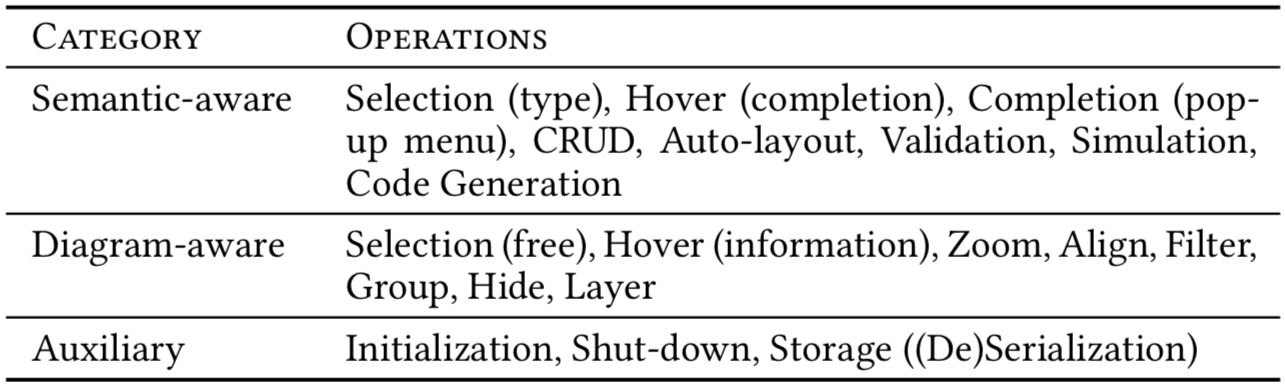
Table 1: Main operations on model editing categorized
The Language Server Protocol
Most textual IDEs are implemented in a programming language different from the language that such IDE supports. In order to reduce the effort for IDE development, editing features can be separated from language semantics. Therefore, at one side, we have a language-agnostic editor (i.e., a generic IDE) and, at the other side, we have a language-specific server; and both are synchronized by means of a protocol. The Language Server Protocol (LSP) is the product of standardizing the messages exchanged between the editor and the server. This architecture also provides developers with the freedom to choose the most suitable technology to implement the client editor and the language server independently of each other.
Figure 1 shows the LSP proposal for programming language IDEs. As can be seen, the client includes a language-agnostic editor which communicates to a language-specific editor server. Editors are responsible for managing editing actions without knowing anything about the semantics of the language. Servers are in charge of language semantics, e.g., they check for the correctness of the source code and correspondingly send any issue to the client to be presented as syntactic errors.
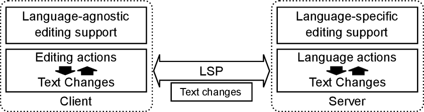
Figure 1: LSP approach for textual programming languages
Currently, LSP has been defined only for text documents, that is, textual programming languages. The concepts used by the protocol are editor (or IDE) “data types” such as the currently open text document (i.e., URI), the position of the cursor (i.e., line and column) or a range of selected text in the editor. This way LSP allows clients to connect to different language servers in a seamless way, thus easily providing support to new languages.
LSP v3.0 defines more than 40 different message types, which describe requests, responses and notifications between client and server sides. Those messages are organized according to their operational scope into five different categories: general, window, client, workspace and document (textDocument).
Motivation for a LSP for graphical languages
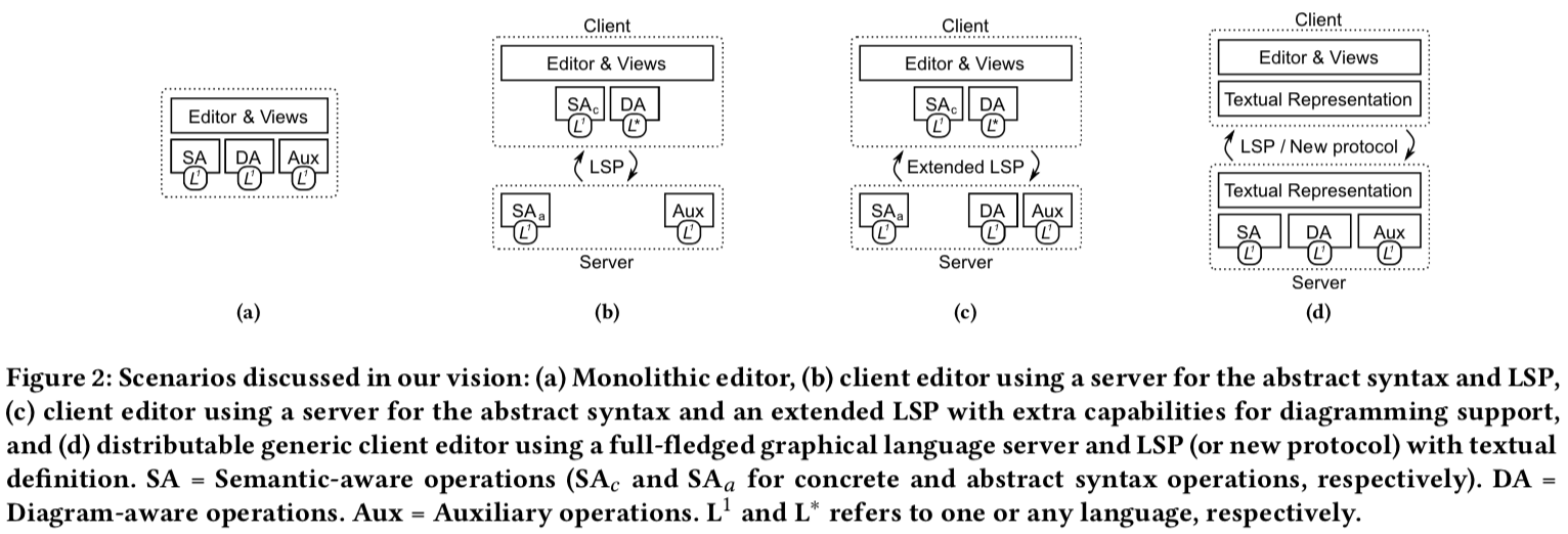
Current graphical modeling editors are generally monolithic solutions covering the main operations identified before, i.e., semantic- and diagram-aware, and auxiliary operations (see Figure 2a).
The main benefit of creating monolithic editors is that they can be tailored to a particular language, which is specially useful for languages with complex concrete syntaxes or semantics (e.g., circuit or architectural languages). Additionally, although their development and maintenance are complex tasks, they are usually built upon existing modeling frameworks (e.g., EMF) and can reuse the plethora of existing modeling tools.
Conversely, as main trade-off, we may highlight the expensiveness of developing model editors (beyond the tree editor) able to deal with different graphical languages at the same time and, therefore, taking into consideration the intricacies of the concrete syntax of each language. This issue is even more severe when we try to use different modeling platforms for the definition of those graphical languages, e.g., in an Eclipse-based environment some graphical languages may use GMF while others Sirius. Monolithic solutions are therefore usually tightly coupled to the development platform, for instance, graphical editors developed in Eclipse depend on the modeling and diagramming frameworks of the platform (EMF and GMF, respectively). Moreover, as indicated by Kahani et al. [8], the potentially brittle plugin architecture of Eclipse is the most common source of headache for users of Model Development Tools, as graphical language editors.
Another important trade-off related to the platform dependency is that they are not distributable, and therefore they cannot be easily deployed in the Web as client editors. Indeed, finding the proper approach to develop and maintain modern Web modeling editors reusing current modeling platforms still remains as a challenge. In the last years, there is an increasing interest to move the modeling editing support to the Web (e.g., the Eclipse Che platform or the Theia prototype), which gives new opportunities, but at the same time, opens new risks and challenges. In a Web-based solution, the deployment of a decoupled architecture composed by client/server is key to provide a performant and usable solution to users. In this scenario, we believe the use of a language server protocol could enable the development of a decoupled solution for graphical modeling languages. This situation also restricts the audience of monolithic solutions and motivates the development of platform-independent editors (e.g., to target users out of the Eclipse ecosystem).
In summary, the main challenges considered are: (1) reducing development and maintenance costs for graphical modeling editors; (2) seamlessly managing different languages developed with different modeling platforms from a single editor; (3) easily using the Web as the platform for modeling editors development and deployment (and thus eliminating installation issues) while reusing modeling frameworks for language servers definition; and (4) providing a single user experience of modeling editors so users can easily deal with different languages by reusing the same set of already known interactions.
Next section describes our vision about how to respond to these challenges by decoupling a modeling editor into a client and a language server, and leveraging LSP to communicate both ends.
Vision for a graphical LSP
In this section we discuss first how a graphical modeling editor could be decoupled into a client editor and a language server and then the protocol that should be deployed to communicate with each other. Although there is a common agreement of the possible benefits derived from this decoupling, currently there is no consensus about how this separation should be performed.
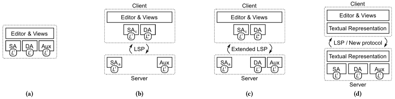
Figure 2: Scenarios discussed in our vision: (a) Monolithic editor, (b) client editor using a server for the abstract syntax and LSP, (c) client editor using a server for the abstract syntax and an extended LSP with extra capabilities for diagramming support, and (d) distributable generic client editor using a full-fledged graphical language server and LSP (or new protocol) with textual definition. SA = Semantic-aware operations (SAc and SAa for concrete and abstract syntax operations, respectively). DA = Diagram-aware operations. Aux = Auxiliary operations. L1 and L∗ refers to one or any language, respectively.
Step 1: Decoupled Architecture
There is a whole spectrum of possibilities to distribute the functionality (i.e., graphical modeling operations) at both sides of a client-server architecture. Figure 2 illustrates four main scenarios ordered according to their level of decoupling: from a monolithic solution (Figure 2a) to a full decoupled solution with a distributable generic client editor and a full-fledged language server (Figure 2d). For the sake of brevity, herein, we are just considering a coarse grained distribution of the functionality of a graphical modeling editor based on the operations we have previously introduced: semantic-aware (SA), diagrammatic-aware (DA) and auxiliary (Aux). Hence, we identify two main scenarios inside such spectrum: (1) partial decoupling, SA (and optionally DA) operations are distributed at both sides (client and server), and (2) full decoupling, where all operations are handled at server side and the client is basically a front-end completely decoupled.
Partial decoupling. In a mid point in the decoupling spectrum, this scenario proposes a graphical modeling editor which manages a single language (or a family of similar languages) but enables Web client deployment by delegating all semantic-aware operations to a language server. Figures 2b and 2c illustrates two solutions for this scenario. The former illustrates a solution where the client provides support only for the semantic operations regarding the concrete syntax of the language (see SAc) plus the diagramming operations. Semantic operations regarding the abstract syntax (see SAa) and auxiliary ones are delegated to the server, which uses standard LSP to communicate with the client. The latter illustrates a similar scenario where an extended version of LSP is used to provide extra support for diagramming operations.
The editor considered in this scenario would be fully aware of the concrete syntax of the language (symbols, compositional rules and mapping), so it can implement more specific capabilities and views at a level close to the monolithic solution. Also, it may be deployed on the Web as semantic-aware operations would be implemented in a different technology stack in a remote server.
This alternative relies on a textual language server (as proposed by LSP) to represent the abstract syntax instances in a textual format. Thus, both client and server share the same text-based abstract syntax instances and rely on LSP for their synchronization.
This case resembles the operational scenario of the LSP-based programming IDEs currently developed. As main advantages, firstly, it may drastically reduce the bandwidth between client and server, because most changes introduced by diagrammatic operations are handled at client side. Secondly, it may provide users with a more specialized experience. Thirdly, it needs a simpler language server, and finally, hybrid representations may be provided to users to deal with. As main drawback, to develop and maintain a client editor for any graphical language is a complex and expensive task. Additionally, those editors cannot easily manage different graphical languages because they would need to implement part of the language support code at client side.
Full decoupling. This case (Figure 2d) illustrates the opposite approach to the monolithic editor: one (Web-friendly) tool to edit and manage any graphical language relying on a server to perform most of the operations.
Decoupling a graphical modeling editor requires both the development of a generic (client) editor parameterized by a language description, which configures the editor including a set of semantic- and diagram-aware available operations; and a graphical language server to provide support for the required operations.
This option enables creating platform-agnostic editors as they can be implemented in a platform different from the language server and contains no dependences to modeling frameworks. As main trade-off, this kind of (client) editor would need a more complex server. A full-fledged graphical language server presents more functionality than textual language servers, basically because it needs, firstly, to provide a richer editing support to encompass two different syntaxes (abstract and concrete), and secondly, to provide a more complex diagramming support to cover semantic- and diagram-aware specific capabilities (e.g., autolayout). However, a great number of modeling frameworks may be reused for the development of that kind of language servers, alleviating considerably the required effort (e.g., GMF for diagram-aware operations).
We consider that a graphical language server must provide (at least) the following capabilities (ordered by dependence): (1) management and validation of abstract model instances; (2) management and validation of concrete model instances; (3) a way to provision of language descriptions (stencil palette & compositional rules); (4) diagram-aware operations (e.g., autolayout); (5) auxiliary operations (e.g., serialization support). Other possible capabilities could include simulation and code generation.
Several levels can be defined regarding the semantic- and diagram-aware operations support at client and server side. For instance, a fully generic editor would delegate any kind of semantic- and diagram-aware operations to the server, while other alternatives could cover some diagram-aware operations such as support for basic layout (e.g., alignment and distribution) or for compositional rules. It is noteworthy that the fewer the operations handled at client-side the greater the number of messages to send to the server. Therefore, at least for Web deployable clients, it seems coherent to provide support to as many operations as possible to reduce bandwidth without compromising editor genericity.
Finally, note that providing the same environment (front-end editor) for any graphical language would promote the same user experience, which may eventually increase the adoption of this kind of tools, as indicated by Kahani et al. [8].
In any of the aforementioned scenarios, a communication protocol is key to allow the language server to communicate with the client editor, which we analyze in the next section.
Step 2: Communication Protocol
We identify three options to use a server protocol for graphical languages, namely: (1) using LSP as it is, (2) extending LSP (i.e., by defining new protocol messages) or (3) defining a new protocol specially designed to deal with graphical languages.
Using LSP. LSP defines a communication protocol between client editors and language servers for programming (textual) languages. This alternative proposes to use LSP as it is, without defining further messages between client and server sides. To give support for the full decoupled scenario (cf. Figure 2d), any operation at client side may need to be mapped into the appropriate LSP message for server synchronization. The main advantages of this approach are:
• LSP is the de facto standard for programming languages. If LSP demonstrates to be enough for graphical languages, there is no need to reinvent the wheel.
• Protocol messages conforms to the LSP specification, thus promoting reusability of tools and frameworks (e.g., LSP4J).
• Future protocol changes (e.g., multitenancy or collaboration support) would be more easily adopted in a compatible way.
On the other hand, we identify the following drawbacks:
• LSP is currently only defined for textual languages, which therefore requires relying on a textual representation format to describe instances of graphical languages.
• Position in a text document is expressed as zero-based line and character offset. Therefore, the client has to map operations expressed in terms of graph nodes/edges into text operations; whereas the server has to map such text operations into model operations. It is therefore key to assess that the chosen textual representation format and protocol messages support every operation, and develop the required interfaces to do the mapping.
• Hybrid representations at client side would require an extra specific language server, because a common textual representation format would be used for any graphical language server.
Extending LSP. In this case, LSP-based approaches defining additional messages for graphical operations are considered. For example, Sprotty, a web-based diagramming framework, is integrated with Xtext, which supports LSP (at server side), and proposes a custom extension of the message to cover specific operations. We identify the following main advantages:
• Hybrid representations are feasible at client side but require some implementation effort to support its representation in the editors.
• All the advantages of the previous alternative.
However, the main drawbacks of this approach are:
• Concrete graphical syntax is defined at client side by means of framework facilities, so the language server is just in charge of the abstract syntax.
• A textual representation for the language is required, which may not be suitable for all the domains. It may imply to make complex your language server because you need to include all the necessary technology stack (e.g., Xtext dependencies).
Defining a new protocol. This is probably the simplest alternative because total freedom is granted. The definition of a new protocol would allow specifying the messages according to the concepts and operations of graphical editors (e.g., node, edge, layout movements, etc.). The client editor, therefore, communicates the language server the editing operations, which the server has to map into model operations. Related to this option, Obeo has been currently working on a specific protocol for graphical languages. However, in its current state, it is still an ad-hoc solution as it relies on a textual representation of the models (i.e., supported by LSP) and protocol messages are only defined to synchronize Sirius-specific editing operations. The main advantages of this approach are:
• Positioning is based on element ids, types and properties. So changes can be indicated as properties of elements, instead of ranges of characters.
• Protocol messages and parameters may be defined to reduce communication overhead, which is interesting when client and editor are deployed in different machines (bandwidth optimization).
On the other hand, the main drawbacks of the approach are:
• Although this option reduces the complexity, it mainly relies on the successful adoption of a new protocol. It is always challenging for a protocol to become a standard.
• Significant overlapping in terms of message definitions as a number of messages such as server initialization or opening a document are common for textual and graphical tools.
• Compatibility with future LSP features (multi-tenancy or collaboration) may be compromised.
In summary, although the pros of defining a new protocol or extending LSP may be substantial, we argue that using LSP itself plus a textual representation is expressive enough for graphical languages, and most of its drawbacks may be properly addressed by providing the needed LSP infrastructure.
LSP Infrastructure for Graphical Modeling
As main goal for our LSP infrastructure, we aim at supporting the scenario shown in Figure 2d, which we consider the most complete and includes the following three main elements: (1) a client, which provides a distributable generic editor for graphical languages; (2) a full-fledged graphical server, which keeps track of every change done in the editor and provides additional capabilities like validation or editing support (e.g., hovering), and (3) the usage of LSP with an intermediate representation format, which represents graphical model instances being edited and shared between client and server. Figure 3 illustrates such scenario (LSP infrastructure is shaded).
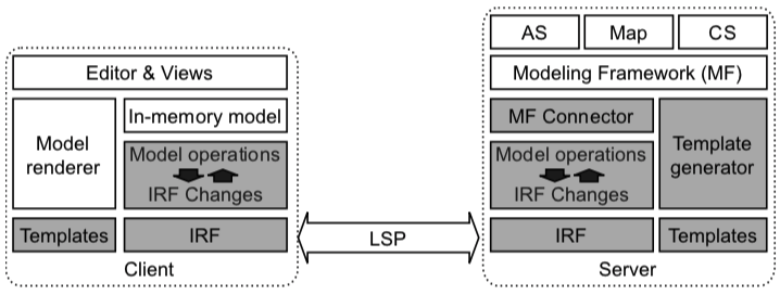
Figure 3: LSP infrastructure proposed. AS = Abstract Syntax. CS = Concrete Syntax. Map = Mapping between AS and CS. IRF = Intermediate Representation Format
Next we describe the intermediate representation format, the server and client of our approach. We finalize this section by showing how LSP and IRF can be used together to provide support for the main graphical editing operations in a full decoupled architecture.
The Intermediate Representation Format
To use LSP for graphical languages we propose the Intermediate Representation Format (IRF), a JSON-based intermediate format to specify graphical models in a textual format. IRF is inspired by existing languages aimed at representing graphs structures [12]. Thus, our language leverages on the concepts of node and edge in a graph. Node represents a graphical element of the model while an edge represents a relationship between two nodes.
A definition of IRF is a JSON object which includes information to represent (1) metadata and (2) a collection of nodes and edges specifying the main elements of the graphical model being edited. In the following, we describe each one of these elements.
Metadata. Metadata includes information about the language which is being edited like the version and the language name (version and language key/value elements of the IRF root object).
Node element. A node represents a model element in the graphical model. It has a unique identifier and a type, which helps the client to locate the graphical definition of the model element.
Edge element. An edge represents a relationship between two nodes in the graphical model. Note that not every edge has a graphical representation (e.g., edges representing a containment relationship between elements). It has a unique identifier, source/target information and a type, which as before helps the client to locate the graphical definition of the relationship. An edge can also group two elements in the model, thus meaning that any editing action (e.g., moving or deleting) may affect both elements.
Nodes and edges also include four sections, namely:
• abstract section, which includes the values for the abstract syntax properties of the element (i.e., one JSON property per attribute owned or inherited by the abstract syntax element).
• concrete section, which includes the values for the concrete syntax properties of the symbol representing this model element (following the same format as in the previous section).
• diagram section, which sets the main layout information of the symbol such as its position and z-order (i.e., order of overlapping elements), when it is a node; or the anchors and the z-order, when it is an edge.
• editorOptions section, which specifies additional behavior information such as whether the graphical element is (1) movable and/or (2) editable.
Note that as abstract and concrete contents rely on the properties of the abstract and concrete syntaxes, respectively, the structure of IRF directly depends on the corresponding abstract and concrete language metamodels. Figure 4 shows an example of the abstract section for a node representing a UML class. As can be seen, there is a JSON key/value element for each (owned or inherited) property of a UML class element according to the UML metamodel. For the sake of clarity we only show an owned property (i.e., isAbstract) and an inherited one (i.e., name). The content of the concrete section follows a similar approach but using a concrete syntax metamodels (e.g., metamodels defined in the context of GMF).
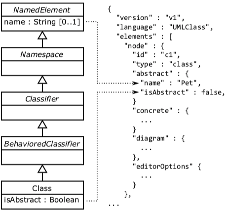
Figure 4: Contents of the abstract section in an IRF node relying on the UML metamodel
At server-side the information of abstract and concrete sections is available directly by accessing to the models of the graphical language (e.g., the abstract/concrete syntax models/metamodels), while at client-side, it is only available through the IRF, which is used to render nodes and edges.
Figure 5 shows an example of the intermediate representation format using a simplified version of UML class diagram as graphical language. The Figure shows, on top, a UML class diagram including two classes called Pet and Owner and one association between them. The class Pet also includes the name attribute. Around the diagram, the Figure shows the corresponding textual representation of the example using our intermediate representation format. The diagram also includes some layout information (e.g., the lengths among elements) to make the mapping between the diagram and the textual easier to understand. For the sake of simplicity, metadata and style sections only show a subset of the abstract and concrete syntax properties, respectively. As can be seen, the textual representation includes: (1) three node elements to represent the two concepts and the attribute, (2) an edge element to represent the association between the two concepts, and (3) another edge element to represent the relationship between the Pet concept and the name attribute, which is not visible but necessary to keep track of the link between the Pet concept and its attributes.
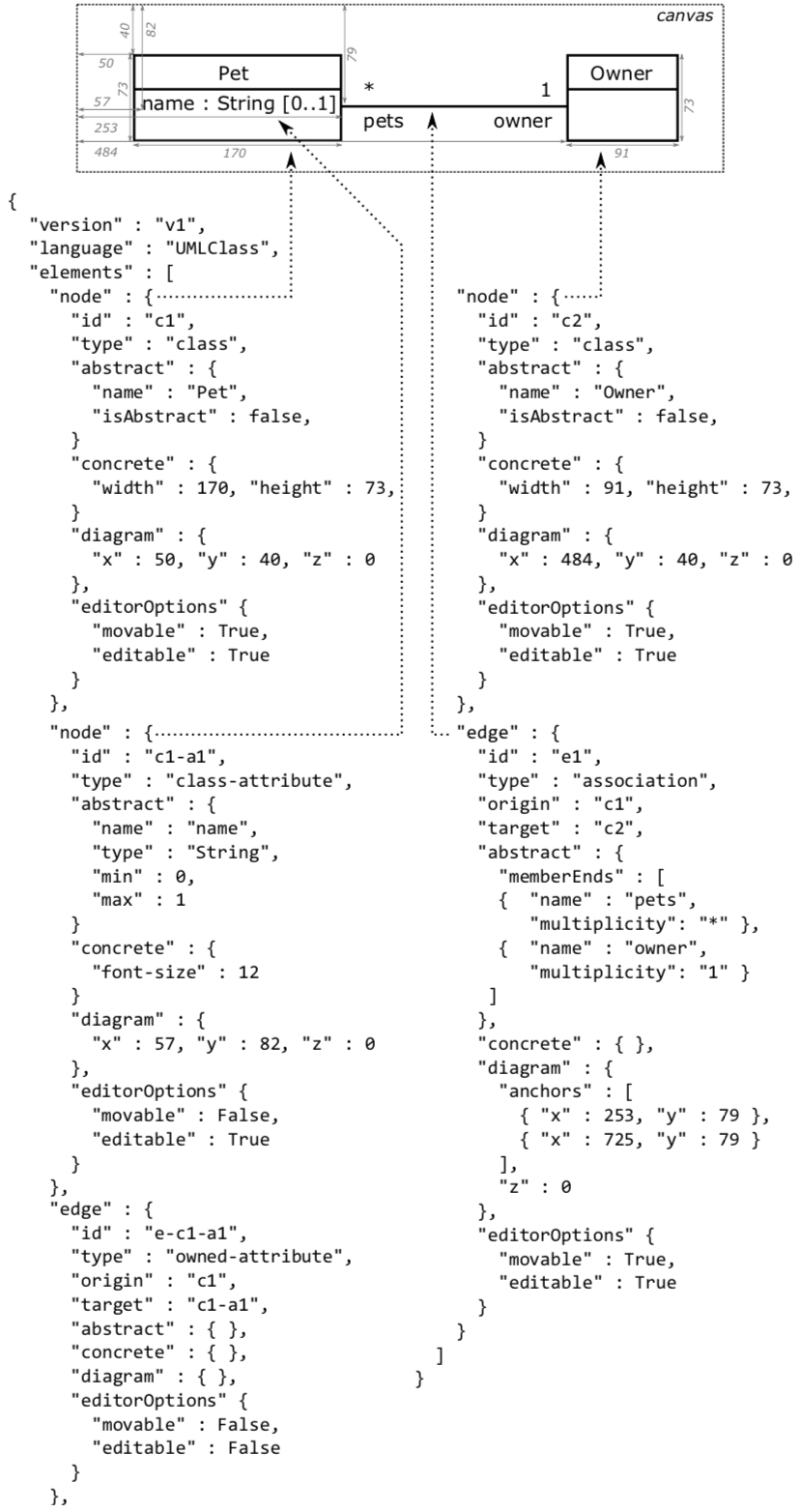
Figure 5: Example of UML Class diagram in IRF
The Graphical Language Server
The server is in full control of what the client editor performs. It therefore has to provide support for the full set of operations in graphical model editing (cf. Table 1). Next, we describe how we propose to address these operations at server-side.
Auxiliary operations provide support for storing and managing graphical language instances. In MDE the abstract syntax of a language is defined by a metamodel, and therefore an instance of the language is stored as a model conforming to such metamodel. Likewise, the concrete syntax of a language is defined by a metamodel, and models conforming to this metamodel are used to store the notation information of a model. Additionally, a mapping between the abstract and concrete syntax is also required. This mapping information specifies the link between notation elements and concepts but also indicates layout information (e.g., how to order the attributes owned by a class in a UML class diagram). As before, the corresponding metamodel/model for defining/storing the mapping information is defined by a metamodel. Thus a specific graphical language instance being edited at the client side would therefore be represented by three models (i.e., abstract and concrete syntax models, and mapping model) at the server side.
To provide support for auxiliary operations, the server has to store and manage both the language metamodel and the corresponding instances. Furthermore, the server has to transform these models into/from IRF (modeling framework connector), which is synchronized with the client by means of LSP. As commented in previous section, the structure of the abstract and concrete sections depends on the abstract and concrete metamodels.
Support for semantic and diagram aware operations control that any editing action is valid according to the semantic of the language. These editing actions involve changes to the IRF shared between the client and the server, which will be eventually validated at server side by means of its model instances (abstract and concrete) and the final modeling framework in use. Finally, the server must provide the graphical definition of the elements being edited (language description) at client side. We propose to follow a template-based approach where templates instruct the client how to render model elements. These templates include placeholders to be filled with the information coming from the fields of the IRF. Figure 6 shows a possible approach for the template-based approach using SVG format as graphical specification format. Figure 6a shows the template to render a UML class diagram, which includes a set of placeholders (surrounded by curly braces) for data from the IRF (e.g., the identifier of the rect SVG element is set to the value node.id). For the sake of clarity, some SVG options and fields have been omitted. Figure 6b shows an instance of such template for the UML class representing the Owner element in the example shown in Figure 5.
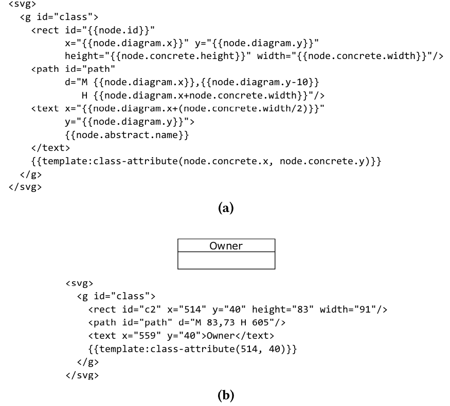
Figure 6: Example of use of templates as graphical definition using SVG. (a) SVG template for a UML class. (b) Instance of the template for a UML class
The Distributable Generic Client
The client provides generic diagramming support for graphical modeling languages. It provides graph-like editor capabilities for graphical models, that is, users can drag&drop elements from a palette to a canvas and modify them (i.e., move, resize, edit, etc.). As commented before, graphical elements are defined following a template-based approach, which allows the client to render nodes/edges. Figure 6b shows the instantiation of the previous template for the Owner class shown previously. The client therefore handles the actions performed by the user, renders the templates and communicates with the server via LSP (see Figure 3).
At client-side, models are represented internally using the intermediate representation format, where nodes and edges are represented according to their type. Unlike textual-based clients, where the code being edited can be serialized as it is; graphical-based clients would require to serialize both the abstract and concrete syntax of the model. Thus, we propose to use the intermediate representation format also as serialization solution for graphical models being edited in the client. Every editing action must be properly translated to changes in the IRF definition and tunneled into the corresponding LSP message by means of the LSP infrastructure. Additionally, extra support could be deployed in the client whether complex serialization is required.
Mapping Operations into LSP+IRF
In this section we assess how our LSP infrastructure provides support for the main editing operations a user can perform in graphical languages. To this aim, we first identify the main operations and then we study how they are tackled by our proposal.
Identification of Operations. In order to collect a comprehensive number of editing operation types, we thoroughly reviewed three MDE graphical edition tools, namely: Papyrus, Sirius and GMF. We follow a methodological approach mainly conducted by two authors of this paper. Firstly, one of them analyzed Papyrus from users’ point of view. Basically, a UML Class Diagram was created by following all the different alternatives Papyrus provides for graphical edition and validation, while he took notes about the workflow and reactions of the tool. Secondly, other author reviewed GMF and Sirius by studying their APIs to discover additional operations. He also took notes about all the different API methods and types that are relevant for graphically editing a model. Finally, both listings were compared and normalized to derive a single one including the main operations for graphical edition tools.
Table 2 summarizes the main operations usually performed in graphical editors as well as the reaction that might be made (covering a valid and invalid action). Note that we just present the main reactions that analyzed edition tools perform to user actions. Most modeling tools usually execute a sequence of actions as a response to an operation triggered by the user. For example, when users choose to remove a concrete node, editors usually proceed with the deletion of all its incoming and outgoing edges.
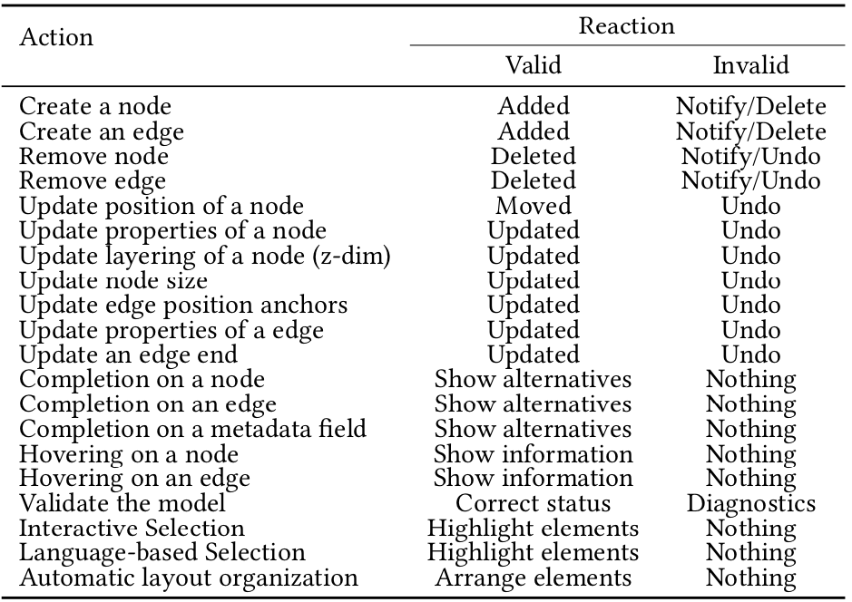
Table 2: Main operations in a graphical editor
Study of Operations. Taking as input the operation list previously presented, we defined a comprehensive set of use cases to illustrate how we can map user operations into LSP messages by leveraging on IRF. Those use cases usually appear in model edition tasks and they have been defined stepwise. Each step tries to isolate every action implying a LSP-based communication between client and server relying on IRF. For example, if a user changes the position of an element in a diagram, then at least two actions must be defined at client-side: (1) communicating the changes to language server, and (2) properly handling the server response.
Table 3 presents a subset of the use cases, and their mapping to LSP messages. Note that the first two rows (labeled as CRU) are representing the first eleven operations in Table 2. For each use case we specify the LSP message sent by the client/server, meanwhile at server-side we indicate the server reaction (if proposed changes are valid/invalid) and the message sent back to the client. We assessed that operations modifying the model (named as CRU) can be mapped to text-based modifications using notifications. In our approach, those text ranges are defined according to IRF definitions and text snippets therefore refer to such definitions. The (de)serialization process is thus key both at client side (to update the diagram displayed to the user) and at server side (to properly update model instances at server side). Note that servers would not reply back when changes create syntactically and semantically valid models, because such models are synchronized and no change needs to be notified. Instead, these changes are communicated to servers by means of a notification and servers can decide if they need to send a message back or not, according to the client capabilities negotiated at the beginning.
The first two rows in Table 3 illustrate two different reactions servers can take when changes introduced to the model are not valid. The first one uses notification to send the list of problems reported at server side. In this case, the client would display the received problems to alert the user. Another alternative is presented in the second row, where the server takes a proactive role removing the last changes introduced by the client. Those new changes are instructed to the client by means of a request, in which ranges of text to be deleted (in the IRF file) are specified.
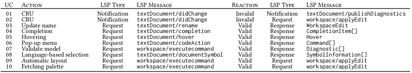
Table 3: LSP mappings
Some LSP messages for language features –such as rename, completion, hover, codeAction and documentSymbol–can also be directly mapped. For example, allows clients to request available commands for a given document/range. These commands are usually presented in form of pop-up menus.
Finally, requests can trigger arbitrary actions at the server, which is suitable for triggering specific modeling tasks such as model validation and obtaining a diagnostic list, triggering an automatic layout algorithm, or obtaining a that implies the modification of different files at client side. Indeed, apart of the IRF file (model representation), it may be used to modify other resources of the workspace as, for example, its element creation palette. A request may be used to fetch palette stencils from the language server and its response, in form of a , may be used to modify a client side resource where stencils are stored. Obviously, it requires those stencils to be textually specified, as we propose.
Two main communication patterns can be extracted from this study. The first one consists on the client sending a notification and the server replying with a notification or a request, depending on the client capabilities. The second one consists on the client triggering an action at server side by sending a request and the server either replying with a request (as action results must be synchronized) or generating a response with such action results.
Example. Table 4 shows an example of use case which illustrates how the creation of a new node in an incorrect position is communicated from client to server by means of LSP messages.
When a user tries to create an element outside of any type, the client updates the IRF definition and those changes are communicated to the language server by means of a notification message. Table 4 shows this communication: the IRF definition before and after the changes (see first column), and the LSP message (see second column). The server performs the changes and launches the validation process, which yields some errors and consequently sends a request to undo the last changes back to the client (see third column). As a result, the modifications instructed by the server involves the removal of the element from the model, so the IRF definition is reverted to its original state.

Table 4: LSP mapping example
As main conclusion, we argued that the combination of LSP and IRF seems to be expressive enough to properly define the communication between the client and server proposed in our vision. As main trade-off, the (de)serialization from graph or model instances to our IRF may be signaled. However, it may be easy to overcome by providing an API hiding this process at client and server sides.
Proof of Concept
We have created a proof-of-concept prototype to test our LSP infrastructure using a simple graphical language including concepts with names and edges between them. The prototype includes (1) a distributable generic client (see Figure 7), which has been developed as a web-based application; and a graphical language server, which relies on the Eclipse platform. Both client editor and language server use the IRF and LSP to represent graphical modeling language instances and communicate with each other, respectively.
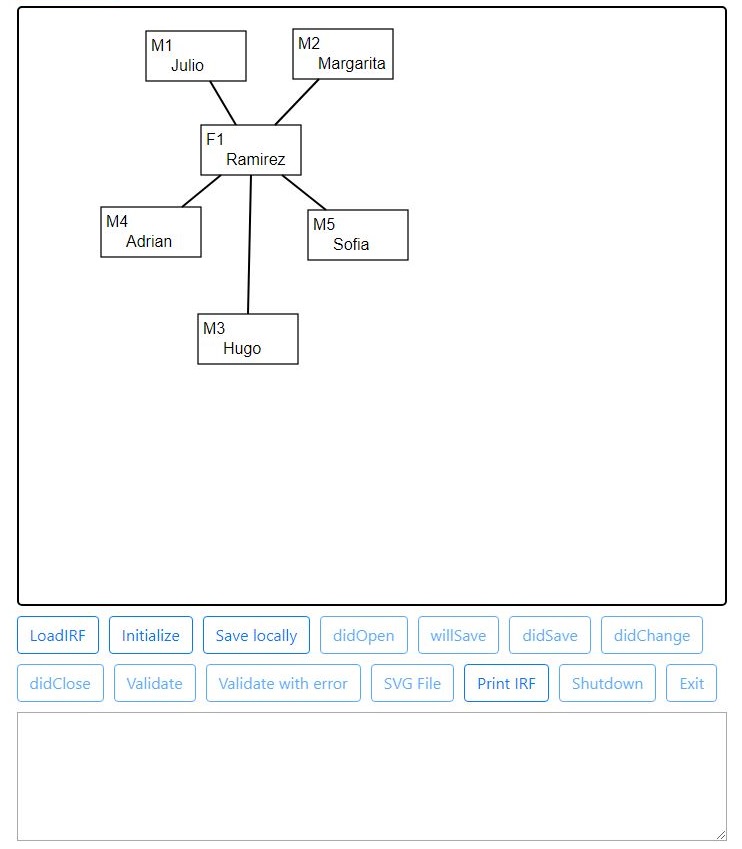
Figure 7: Generic LSP client
The website developed for the client side part has been implemented using standard Web technologies (i.e., HTML, CSS, SVG and JavaScript). The diagramming support of the client editor relies on JointJS, a free diagramming library developed in JavaScript. As commented before, the client keeps an instance of the graphical modeling language expressed in IRF, which is synchronized with the server by using LSP. Thus, events and editing actions in the diagram update the IRF definition of the instance.
To enable genericity in the client, the symbols of its diagram palette are retrieved from the server. The server publishes a set of SVG-based templates for the language concepts via a specific LSP command, while the client renders language symbols by injecting the information represented in the IRF definition into the SVG templates, as described before. These templates are used to configure the JointJS-based diagram editor, thus the user can drag&drop them to create instances of the graphical language.
The language server relies on the Eclipse Modeling Framework (EMF) and the Graphical Modeling Framework (GMF) to provide model management, validation and storage of graphical languages. While EMF offers the core support to manage and validate models and metamodels, GMF provides the required support to define the concrete syntax of graphical languages. Figure 8 presents our LSP-based graphical language server architecture.
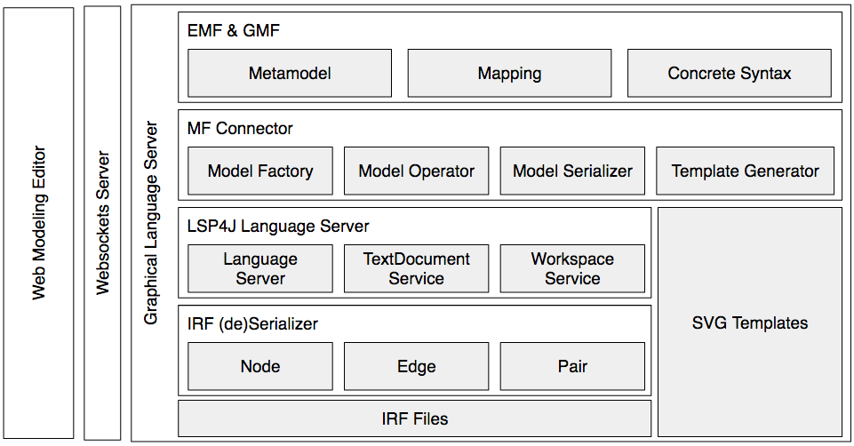
Figure 8: LSP-based graphical language server architecture
Related Work
The use of LSP for programming languages is an emerging working area where companies are addressing the development of language servers for well-known languages. There are also similar efforts for the development of language servers for textual domain-specific languages, like the support provided by Typefox using Xtext (i.e., the framework generates the server for any Xtext-based language). However, to the best of our knowledge, little attention has been paid for the development of client/servers for graphical languages.
Only a few initiatives aim at protocol-enabled client-server solutions, namely: Obeo, Sprotty and Eclipse Che. Obeo proposes a solution relying on an extension for LSP for graphical languages, which corresponds to the third scenario commented in Section Vision (cf. Figure 2c) This initiative was released in March 2018 and is still under heavy development, it reveals the increasing interest of the industry to provide a solution for graphical languages.
Typefox is developing Sprotty, a framework which offers a web-based environment for graphical languages. The tool relies on Xtext and LSP to synchronize a textual language instance between client and server, which is then rendered at client-side to show a diagram projection. The projection is only a view and therefore no edition is allowed. This alternative can be considered a partial solution (i.e., only a projection is provided) and extra effort is still required to support the full range of graphical language operations.
Eclipse Che is maybe a special case, as it aims at providing an IDE in the Cloud. Eclipse Che incorporates a server which provides the set of IDE capabilities of the original desktop-based Eclipse. The server can also connect to LSP language servers to provide support to additional textual programming languages. At the client-side, developers can connect to the Che server via web-browsers to work with these LSP-enabled languages. Thus, Eclipse Che actually works as a generic client for textual LSP language servers. However, the support for graphical languages is still very limited.
Our work is also related to those approaches developed to deliver modeling functionality as a service [13] (a.k.a., Model as a Service, MaaS). In MaaS, models are stored remotely (e.g., on the Cloud) and its capabilities are accessed via API (i.e., as services). It is therefore common to develop a client-server (or Cloud) infrastructure to enable MaaS. A MaaS approach can cover any modeling functionality (e.g., model storage, using CDO or Morsa [5]; or code generation as described by Crocombe et al. [2]) but we are specially interested in the support for designing and creating graphical models. Thus tools such as AToMPM [15], GenMyModel [3] and WebGME [11] propose client-server solutions where users can create and edit instances of graphical modeling languages. However, all of them rely on proprietary protocols for the client-server communication.
Several works propose the development of stand-alone Web-based modeling environments (e.g., [10,6, 14, 17, 19]). These kind of works provide full editor environments for specific languages, which corresponds to the monolithic editor we commented in Section [sec:motivation] but in the Web. On the other hand, there are also proposals to facilitate the development of server-side modeling tools by generating the required infrastructure for basic model management such as storage and/or validation (e.g., EMF-REST [4] or Texo).
Our IRF proposal is related to works providing a textual format for models, including: (1) model serialization formats like XMI, (2) specific metamodels (e.g., those used in Sirius and Papyrus for diagrams) and (3) standard specifications like OMG’s Diagram Interchange Format [12]. Also, the work by Tendeloo et al. [16] proposes a JSON-based bidirectional mapping between abstract and concrete language syntaxes which can also be used as representation format for models. The IRF structure has been inspired by these works.
Conclusion and Future Work
In this paper we discussed different alternatives of clients, servers and LSP usages for decoupling graphical language tooling. We described an approach relying on standard LSP and a text-based model representation shared between clients and servers, plus a proof-of-concept. As future roadmap to advance further in the simplification of graphical modeling editors and the validation of the presented approach, we envision the following working lines.
Generation of language servers. An automatic approach to generate the required server implementation would promote the adoption of decoupled solutions. This implementation could be derived from a textual definition of the language abstract and concrete syntaxes (e.g., the one used in the Collaboro approach [7]). In our LSP infrastructure, it could be generated: (1) the modeling framework connector for the specific language (i.e., IRF (de)serialization), and (2) the language description in SVG format (i.e.,template generator).
Generic client editor validation. In this work we argued that a generic client editor is a promising path to follow to reduce development costs and users’ learning curve. However, those claims need to be properly validated. Are there any technical limitations for a client editor using multiple graphical languages at the same time? Can users effectively reuse their previous knowledge of the tool to edit models conforming to a different language?
Performance assessment. LSP-based client-server synchronization in a fully decoupled scenario (i.e., both ends are deployed in different systems) may entail a high bandwidth consumption and therefore significantly impact the editor performance. Further studies in real cases should be carried out to identify performance issues and derive proper optimizations for the LSP infrastructure.
Multitenancy and collaboration. These features are crucial when performing modeling tasks however they are not currently supported in LSP. Nevertheless, the LSP community is planning to cover these features in the future. As our approach relies on standard LSP we plan to follow suit and make sure we can benefit from them to provide also multitenancy and collaboration for graphical languages, adapting our current proposal (e.g., the IRF) as needed.
References
[1]Brambilla, M. et al. 2012. Model-driven software engineering in practice. Morgan & Claypool Publishers.
[2]Crocombe, R. and Kolovos, D.S. 2015. Code Generation as a Service. Int. workshop on model-driven engineering on and for the cloud (2015), 25–30.
[3]Dirix, M. et al. 2013. An Online UML Case Tool. Europ. conf. on object-oriented programming (2013).
[4]Ed-Douibi, H. et al. 2016. EMF-REST: Generation of RESTful APIs from Models. Symp. applied computing (2016), 1446–1453.
[5]Espinazo-Pagán, J. et al. 2015. A Repository for Scalable Model Management. Software and System Modeling. 14, 1 (2015), 219–239.
[6]Hiya, S. et al. 2013. clooca : Web based tool for Domain Specific Modeling. Demo at int. conf. on model driven engineering languages and systems (2013), 31–35.
[7]Izquierdo, J.L.C. and Cabot, J. 2016. Collaboro: a Collaborative (Meta) Modeling Tool. PeerJ Computer Science. 2, (2016), e84.
[8]Kahani, N. et al. 2016. The Problems with Eclipse Modeling Tools. Int. conf. on model driven engineering languages and systems (2016), 227–237.
[9]Kleppe, A. 2008. Software language engineering: Creating domain-specific languages using metamodels. Addison Wesley.
[10]Leal, J.P. et al. 2016. Eshu: An Extensible Web Editor for Diagrammatic Languages. Symp. on languages, applications and technologies (2016), 12:1–12:13.
[11]Maróti, M. et al. 2014. Next Generation (Meta)Modeling: Web- and Cloud-based Collaborative Tool Infrastructure. Workshop on multi-paradigm modeling (2014), 41–60.
[12]OMG 2006. UML Diagram Interchange. OMG.
[13]Popoola, S. et al. 2017. Modeling as a Service: A Survey of Existing Tools. Int. conf. on model driven engineering languages and systems (2017), 360–367.
[14]Rose, L. et al. 2012. EuGENia live: a flexible graphical modelling tool. Workshop on extreme modeling (2012), 15–20.
[15]Syriani, E. et al. 2013. AToMPM: A Web-based Modeling Environment. Demo at int. conf. on model driven engineering languages and systems (2013), 21–25.
[16]Tendeloo, Y.V. et al. 2017. Concrete Syntax: a Multi-paradigm Modelling Approach. Int. conf. on software language engineering (2017), 182–193.
[17]Thum, C. et al. 2009. SLIM – A Lightweight Environment for Synchronous Collaborative Modeling. Int. conf. on model driven engineering languages and systems (2009), 137–151.
[18]Vuyović, V. et al. 2014. Sirius: A rapid development of DSM graphical editor. Int. conf. on intelligent engineering systems (2014), 233–238.
[19]Wimmer, M. et al. 2017. Towards Automatic Generation of Web-Based Modeling Editors. Int. conf. on web engineering (2017), 446–454.
Roberto Rodriguez-Echeverria is associate professor at the University of Extremadura (Spain) and actively collaborate with SOM Research Group (IN3 UOC). His main research lines are Model-Driven Engineering, Open Data, Web Engineering, and Reverse Engineering.


Dear Roberto,
thank you very much for sharing this insight into your quite interesting research! From the perspective of a tool provider we’ve experienced much of the mentioned pain of developing own tools and we are truly looking forward for such graphical modellers as proposed here.
I’d like to mention a few thoughts from our experience, with respective, not completely unselfish hopes of possible consideration in mind:
1. Rendering: with a SVG/template based approach it is already possibly to apply CSS styling to models. This could be driven one step further: using abstract-to-concrete-model-rendering cascading style sheets (“A2CCSS”). This is comparable to the rendering of data oriented XML within browsers. Such a style sheet might look like this (this example defines the rendering of a UMLClass):
svg UMLClass {
svg-tools:true
svg-shape-template:my.path.templates.shapes.SVGRectangle
svg-content-template:my.path.templates.SVGCompartments
svg-corner-radius:0
svg-parallel-strokes:0
svg-head-attributes:stereotypes;secondary;placeholder:«${text}»,name,templates;secondary;placeholder:◁ ${text} ▷
svg-compartment-attributes:attributes;List#operations;List
}
The example makes use of two configurable common templates ‘SVGRectangle’ and ‘SVGCompartments’. This would encourage the creation of a common library of modelling templates, but still allow to define customised ones. In addition to being ‘cascading’, these stylesheets should also treat the selectors as objects, i.e. that a CSS rule for say an ‘UMLElement’ would automatically apply to a ‘UMLClass’, which even more simplies the stylesheets.
2. Flexible Editor Architecture
We understand the difficulty of the question where to best make the cut between server and client. After many years of the IT industries oszillating between ‘more on the server’ and ‘more on the client’, an answer might be to leave this decision open, since there seems to be no ‘one size fits all’ solution. I just checked the LSP tool page, it’s funny to see about 4 (!) emacs bindings, so purely text based old style is not dead at all. On the other side, a mobile App, working without server connection and storing it’s model locally in a git repository, to be synchronised at a different point in time, is also a fairly reasonable usage scenario today.
Therefore, it might make seens to in addition (!) to the more concrete-model oriented LSP communication style (with nodes and edges as primary artefacts) also support a more abstract-model oriented style, which is e.g. rendered on the client side with help of such “A2CCSSs” into a conrecte model, which is then rendered to e.g. SVG or whatever.
Such an abstract-model oriented protocol would also enable the creation of non-graphical editors for servers using one and the same protocol.
3. UX and Extensibility
The main driving factor behind our own modeller developments has been always customer UX expectations. We (as technically oriented minds) never had really much difficulties of working with standard editing tools, but the more domain oriented customer always had.
Therefore, I think that next to a generic editor solution there must be effective means of extensibility. To not to be misunderstood: for standard UML or BPMN of course a standard editor will be sufficient, but not for languages aiming at defining more complete systems, up to fully model based solution creation.
Extensibility is desirable in to ways: the first would be the equivalent to ‘Macros’ in text based languages, i.e. the capability of easily define language extensions within the modelling frontend, without access to the language server. This could be something of a DSL flavour, to be able to optimise the graphical editor for a given usage.
The other kind of extensibility is augmentation of the modeller with arbitrary extensions. These can be of course coded and plugged in into respective extension points, but this would imply to become editor implemention environment specific again, which is no desirable. An intermediate form of support would be much helpful here, something like an abstract description of additional dialogs/editing operations.
Kind regards
Andreas
[email protected]
Dear Andreas,
First of all, thank you for your interest and sorry for the delay in my response.
1. A2CCSS sounds interesting as a mean of providing different styles to an abstract syntax. However concrete syntaxes concerns are not only a matter of how model elements are presented to the user, but also which operations are available, which constraints should be satisfied, and what semantic (abstract model) consequences may imply a specific operation in the diagram, e.g. if you draw a UMLClass on a UMLPackage, it may entail such UMLClass instance must be included in that UMLPackage instance (the UMLClass box is completely contained inside the UMLPackage box) or not (the UMLClass box is NOT completely contained inside the UMLPackage box). Anyway for styling concerns A2CCSS may be an interesting approach.
2. Regarding the flexible editor architecture, as current LSP-based approaches usually do in the case of programming languages, it’s possible to deploy both client and server as two different systems in the same machine/device and connect them by IPC. Therefore, you might use all the server capabilities in an offline operation mode. If the target device capabilities constraint server functionality, you might use a light version of such server without changing the client editor. Ideally, by using the same protocol (LSP), you have the chance of connecting any client editor you have to any version of your language server.
To sum up, you can “always” deploy a proper version of your language server together your client editor to delegate concrete concerns of your model/diagram.
I may be missing your point here, but I cannot clearly see the necessity for this abstract-model oriented protocol. Maybe you mean our model representation named IRF. In such case, we think an IRF instance should include all the abtract and concrete properties of your model to be ready for the different client-server distribution scenarios. In any case, the client editor will handle the communication with the language server, so it might (or not) delegate concrete syntax handling to the server.
3. I agree. Extensibility is a key point for modelling tools (client editors). I find really interesting the first idea you named “Macros”. I guess you are talking about defining your own templates/patterns to speed the use of a concrete language for a specific domain. I think this is related to another work I’ve recently published in the context of IFML: “AutoCRUD: Automatic generation of CRUD specifications in interaction flow modelling language“.
Thank very much for your interesting comments.
Best regards,
Roberto
Dear Roberto,
thank you for your response. Certainly the ideas mentioned above are by far not mature ones, what I have in mind is, given that graphical-LSP is intended to be a foundation for general purpose modellers and a large variety of backends, for possibly a long time to come, it makes sense to consider requirements like these as early as possible.
Concerning (1), of course concrete syntax is more about than just styling. This can be considered in templates, but it can also be partially derived automatically from information of the abstract syntax. E.g., a UMLPackage will expose some kind of editable association to the UMLClass, then annotating this association with just a style like “visible container pane” could provide all the necessary hints for the UI to draw some area along with operations like drag and drop, right click popup menu “add and place here” etc. This has many advantages: it reduces development efforts (only once for the UI, compared to repeatedly for each and every backend), plus simplified recognition of UX patterns for the modeller, since such operations would be implement each time in the very same way.
As for (2), what I had in mind here is something like a Progressive Web App (it would be a dream to have a good UX/UI standard modelling tool based on this, fitting to browser as well as Mobiles), where deployment of a separated LSP server might be a bit difficult; plus the observation of the general trend to much more do in the frontend code and communicate with servers more data oriented; Of course, all these are not hard requirements, it’s more like thinking: there are a lot of implicit assumptions about ‘graphicalness’ of the models to be manipulated, and I wonder whether these assumptions are stable enough. E.g., I might want to manipulate one and the same model with a graphical modeller and with a text language. In the latter case, a graphical oriented protocol would be rather difficult to use in a text editor. This is not say at all that a graphical oriented language is superior/inferior to an AS oriented language, instead I would consider both as desirable, as well as a standard/default translator from the one to the other.
As for (3), yes, the purpose is easiness, speed, flexibility for the modeller, thank you for the link to that paper!
Kind regards
Andreas