For many in the Business Process Modeling/Management (BPM) community, the term “process” is synonymous with “business process”. But, ontologically, there are different types of processes, and business processes are only one special type of process.
Processes are characterized through the state changes they bring about, and since state changes are either continuous or discrete, we have to distinguish between two fundamental types of processes: continuous processes and discrete processes. For instance, in production management, they distinguish between
- process manufacturing (e.g., of sugar or chemical liquids) with continuous processes modeled by differential equations, which can be described by stock-and-flow diagrams, and
- discrete manufacturing (e.g., of cars or phones) with discrete processes modeled with the help of a discrete process modeling language.
We can therefore describe a business process (BP) as a discrete process that involves business activities performed by organizational agents qua one of their organizational roles defined by their organizational position. While there are many discrete processes that do not have an organizational context (like, for instance, the operation of an elevator, message exchange processes in digital communication networks or private conversations among people), a BP always happens in the context of an organization.
The Evolution of Discrete Process Modeling Languages
Historically, the first examples of discrete process modeling languages are Gantt charts, Process Charts and PERT/GERT charts, which have been developed in the 1910’s, 1920’s and 1950’s/1960’s, respectively, in the fields of Industrial Engineering and Operations Research. A high number of different types of flowcharts has been proposed in the sequel, also for the purpose of describing algorithms in Computer Science, leading to an ANSI/ISO definition in the 1960’s/1970’s. Gantt and PERT charts are based on concepts of activities and their temporal sequencing including parallel branching, but they do not support events and conditional branching. Flowcharts are based on concepts of activities and their temporal sequencing, including conditional branching, but they do neither support events nor parallel branching. GERT charts essentially extend PERT charts by adding conditional branching.
Petri Nets have been developed as a modeling language for distributed systems in the 1960’s, based on the abstract computational concepts of “places”, “tokens” and “transitions”. While Petri Nets have been proposed to be used as a business process modeling language only later, in the 1990’s, Event Graphs have been proposed as a modeling language for discrete processes based on the concepts of events, state changes and causation in the 1980’s, already.
Unfortunately, Event Graphs have only become well-known in the areas of Operations Research and Discrete Event Simulation, but have been largely ignored in Computer Science and Informations Systems. As a consequence, the abstract formalism of Petri Nets has been widely adopted as the standard semantics of business processes in the BPM community, despite the fact that Event Graphs would have been a much more natural choice, since they refer to the ontological foundations of discrete processes: events, state changes and causation.
BPMN can be viewed as the culmination of the efforts to define more expressive flowcharts. It supports the concepts of events and activities and their temporal sequencing, including conditional and parallel branching. But BPMN has several severe issues:
- Its “Sequence Flow” arrows are heavily overloaded and do not have a clear meaning.
- Its resource modeling capabilities are severely limited, despite the fact that it is supposed to be a business process modeling language. It does not support the essential resource modeling concepts of passive resources, resource cardinality constraints, multitasking constraints, task priorities and activity preemption.
- It does not have a convincing formal semantics. Its official token-flow semantics is rather ad-hoc, while academic proposals for a formal semantics are indirect/translational and diverge from each other.
The Discrete Event Process Modeling Notation (DPMN)
The Discrete Event Process Modeling Notation (DPMN) combines the formally precise language of Event Graphs with the intuitive flowchart notation of BPMN and solves all the issues of BPMN listed above. DPMN supports three types of discrete process models: Object Event Graphs, Activity Networks and Processing Networks.
DPMN is based on the Object Event Modeling and Simulation paradigm (OEM&S). It can be used as a process modeling language in Information Systems Engineering and BPM, as well as in Discrete Event Simulation.
From Event Graphs to Object Event Graphs
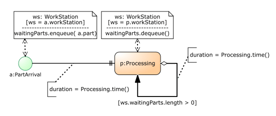
In Event Graphs, the state structure of a system is described with state variables. Since it is desirable (and more natural) to describe the state structure of a system with object types and their attributes, Event Graphs have been extended to Object Event Graphs in DPMN. An example of an Object Event Graph is shown in the following figure.

This diagram, which is based on an underlying UML class model defining the types of its objects and events, describes the operation of a manufacturing workstation by specifying three event rules, one for each event circle:
- When a PartArrival event occurs, the arrived part is enqueued in the waitingParts queue of the workstation where the part arrived (this is the state change of the affected WorkStation object specified in the corresponding DataObject rectangle attached to the PartArrival circle). If the value of the workstation’s status attribute is AVAILABLE, then a ProcessingStart follow-up event is scheduled to occur without any delay.
- When a ProcessingStart event occurs, the workstation’s status attribute is set to BUSY and a ProcessingEnd follow-up event is scheduled to occur with a delay obtained by invoking the function processingTime (defined in the class ProcessingStart) implementing a random variable.
- When a ProcessingEnd event occurs, the next part is dequeued from the waitingParts queue and if the resulting queue length is 0, then the workstation’s status attribute is set to to the value AVAILABLE. If the queue length is greater than 0, a ProcessingStart follow-up event is scheduled to occur without any delay.
You can run this model from sim4edu.com.
A set of object and event types, specified by a UML class model, together with such a set of event rules, specified by an Object Event Graph, defines an Abstract State Machine, which is a very expressive type of state transition system, as explained in the section The OES Formalism in my book Business Process Modeling and Simulation with DPMN. In this way, a direct formal semantics for DPMN is obtained.
Notice that the arrows in an (Object) Event Graph conceptually denote causal links, while they computationally denote event scheduling according to the Event Scheduling paradigm of Discrete Event Simulation where follow-up events are scheduled by adding them to a Future Events List.
From Object Event Graphs to Activity Networks
It is well-known that an activity is framed by a pair of events: an activity start and an activity end event. Whenever there is such a pair of events in an Object Event Graph, it can be replaced with the corresponding activity. The resulting model is no longer an Object Event Graph, but an Activity Network consisting of two kinds of nodes (events and activities) and their temporal sequencing via event scheduling arrows.
For instance, the Object Event Graph shown above contains event circles for such a pair of events: ProcessingStart and ProcessingEnd representing a Processing activity. Consequently, these two event circles can be replaced by an activity rectangle, as shown in the following Activity Network DPMN diagram:

Whenever an activity of a certain type is to be performed, various resources may be required for performing it and have to be allocated first. We can distinguish between ‘active’ (or performer) resources, such as human resources, robots or IT systems, which execute activities, and ‘passive’ resources, such as rooms or devices, which are used by performers for executing activities.
When a person, as an organizational agent, performs an activity within a BP, the person is a resource. When a person performs an activity within a discrete process that is not a BP (e.g., laughing in a conversation), the person is the performer of the activity, but not a resource of it. Consequently, while all business activity types are resource-constrained, there are also activity types that are not resource-constrained.
The performance of a resource-constrained activity is constrained by the availability of the required resources. For providing the resources required for performing its business processes, an organization maintains resource pools.
The dependency of an activity on resources is modeled with the help of resource roles, which are special properties of an activity type. For a DPMN process model, resource roles are defined in the underlying UML class model in the form of an association between the class representing the activity type and the class representing the resource object type. The multiplicity of the association end at the side of the resource object type defines resource cardinality constraints, while the multiplicity of the association end at the side of the activity type defines a multitasking constraint.
For instance, the following class diagram states that the activity type “load truck” has a resource role “wheel loaders” with a resource cardinality constraint of 1..2 meaning that “at least one and at most two” wheel loaders are required/admissible for a “load truck” activity. In addition, the multiplicity 0..1 at the other association end defines a multitasking constraint stating that a wheel loader can be used in at most one “load truck” activity at the same time.
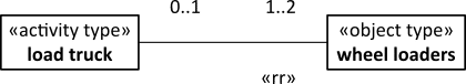
Notice that the association end at the side of “wheel loaders” is categorized as a resource role by the UML stereotype «rr».
A workflow model is a BP model that only involves (typically human) performer resources. Examples of industries with workflow processes are insurance, finance (including banks) and public administration. Most other industries, such as manufacturing and health care, have business processes that also involve passive (non-performer) resources.
In BPM, there is a tendency to consider workflow processes as paradigmatic for business processes. However, workflow processes only have (human) performer resources, while business processes in general often have one or more passive resources in addition to a performer. Due to this tendency, BPM research often adopts a simplistic view of business processes.
Introducing Resource-Dependent Activity Scheduling Arrows
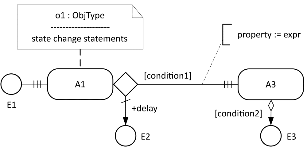
In an Activity Network, a resource-constrained activity can only be scheduled with an event scheduling arrow, if the event scheduling arrow is conditional and its condition makes sure that all resources needed for performing the activity have been allocated to it, requiring that the predecessor event attempts to allocate the needed resources. The implied resource dependency management modeling pattern creates boilerplate modeling elements, which can be replaced with a new modeling element in the form of Resource-Dependent Activity Scheduling (RDAS) arrows with three bars as their arrow head symbolizing a task queue, as shown in the following diagram.
Using an RDAS arrow from PartArrival to Processing allows simplifying the previous model by dropping the model elements that have taken care of resource dependency management.
From Activity Networks to Processing Networks
A Processing Activity is a resource-constrained activity that takes one or more objects as inputs and processes them in some way (possibly transforming them). Processing activities typically require immobile physical resources, like rooms or machines, which define the inner nodes of a Processing Network. A Processing Object enters such a network via an Arrival event at an Entry Station, is subsequently routed along a chain of Processing Stations where it is subject to Processing Activities, and finally exits the network via a Departure event at an Exit Station.
Each node in a Processing Network model represents a combination of an object and an event type. An Entry Node represents a combination of an Entry Station (e.g., a reception area) and an arrival event type. A Processing Node represents a combination of a Processing Station (e.g., a workstation or a room) and a processing activity type. An Exit Node represents a combination of an Exit Station and a departure event type.
These new DPMN modeling concepts are illustrated in the following Processing Network version of our running example model.
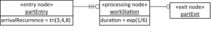
A Processing Flow arrow connecting a Processing Node with another Processing Node or with an Exit Node represents both an event flow and an object flow. Thus, the node types and the flow arrows of a Processing Network are high-level modeling concepts that are overloaded with two meanings.
While an Activity Network model is only concerned with the temporal sequencing of events and activities, and its nodes do not imply any spatial locations, the nodes of a Processing Network define locations in a network space. This implies that there is a natural visualization for simulation runs of a Processing Network where we can see processing objects flowing through the model’s network space.
Processing Networks are the main paradigm in Discrete Event Simulation (DES). DES tools, such as Arena, AnyLogic, FlexSim and Simio, use their own proprietary terminology and diagram languages for Processing Network concepts and models. The OEM&S concepts and terminology, as well as the diagram language of DPMN provide a foundation for developing a standard for Processing Network modeling and simulation.
Processing activities are specialized by transformation activities, which take one or more input objects of various types and transform them into one or many output objects of various types. How to integrate transformation activities in DPMN Processing Networks is a topic for future research.
DPMN Tooling
Unfortunately, a DPMN diagram editor is not yet available. However, Object Event Graphs can be created with a BPMN diagram editor (the Object Event Graph shown above has been created with Signavio). For creating Activity Network diagrams with RDAS arrows, and for creating Processing Network diagrams MS Visio can be used.
For executing a process simulation model created with DPMN, the OESjs simulation framework can be used. OESjs is a JavaScript implementation of the OEM&S concepts, such that a DPMN model can be directly coded with it. The sim4ed.com website provides examples of (1) Object Event Graph models, (2) Activity Network models and of (3) Processing Network models.
Outlook
It should be clear that the “logic” of process modeling is much more complex than the logic of state structure modeling (e.g., with UML class models). For instance, while it seems pretty clear that UML 2.5 class modeling captures the core of domain-independent state structure modeling concepts, it is much more unclear what constitutes the core of domain-independent process modeling. For instance, do agent-oriented modeling concepts belong to such a core? In BPMN, there are some rudimentary forms of agent-oriented modeling: Pools/Lanes may represent agents, asynchronous message exchanges may represent agent communication, and Choreography models may represent agent communication protocols.
There are several open issues in OEM&S/DPMN where more research (and development) is needed, and where contributions by other researchers are welcome:
- How to support event canceling (e.g., for preventing already scheduled machine failure events)?
- How to integrate transformation activities in DPMN Processing Networks?
- How to develop a full account of agent-based (business) process modeling? Notice that there is already a basic account of agent-based modeling and simulation.
- How to develop a process mining approach for DPMN models? This implies using a rich concept of event/process logs with state changes of resource objects, processing objects and other affected objects, and with the distiction between plain activities and processing activities.
Also, while a language like DPMN can provide a common foundation, there are many domains (e.g., manufacturing, healthcare or AI Engineering) that may require domain-specific process modeling concepts. Consequently, it will be important for any process modeling language to have suitable extension capabilities.
Gerd Wagner is Professor of Internet Technology at Brandenburg University of Technology, Cottbus, Germany. After studying Mathematics, Philosophy and Informatics in Heidelberg, San Francisco and Berlin, he (1) investigated the semantics of negation in knowledge representation formalisms, (2) developed concepts and techniques for agent-oriented modeling and simulation, (3) participated in the development of a foundational ontology for conceptual modeling, the Unified Foundational Ontology (UFO), and (4) created a new Discrete Event Simulation and IS modeling paradigm: Object Event Modeling and Simulation (OEM&S), which includes a new process modeling language: the Discrete Event Process Modeling Notation (DPMN). He also runs the websites dpmn.info, web-engineering.info and sim4edu.com.

Recent Comments