

The last post on miotope (November ’18) presented the first part of a “Walkthrough of the Modelling Arena”, starting with IT System Architecture. Upcoming parts shall cover more areas where modelling plays a role in an organisation: Business Systems, Landscapes, Infrastructure, Descriptions, and Lightweight Collaboration; with a certain IT bias in mind. This shall serve to clear the ground for a refactored language capable of growing a modelling biotope.
The feedback I received to this last article showed: there is more or less consensus about the description of the problem, but it wasn’t clear how precisely the described concepts possibly could help to solve it. Therefore, before continuing the walkthrough, I’d like to give an answer to this question. Necessarily, this anticipates the overall sketch of the Modelling Arena a little.
Specifically, this post is about 1. the notion of Generic User Interfaces (what it meant and what it might mean), 2. a clearer coining of some terms (my personal understanding of certain Development Artefacts and Activities), and 3. an example to illustrate a possible application of the ideas.
The example is mainly based on experiences with our EM/OS – Enterprise Model Operation Services technology, a modelling solution that continuously evolved since around 1995. I took the freedom to polish the code a little for the sake of clearness and with the goal of a “fresh start” in mind.
User Interfaces: Automation, Architecture and Art
The notion of a Generic User Interface seems to rise ambivalent connotations, depending on the background, experiences and cultural IT biases of the audience. Clearly a single term denoting evolving approaches spanning three decades of digital history must fail its purpose: there is a difference between an ’80ies green screen form automatically derived from a database schema on the one hand side and a late ’10s well designed, progressive, responsive, reactive app based on a famous framework on the other.
The core controversy could be summed up like this:
- UI crafting is an art, not an engineering job
- UI crafting is a tedious, highly repetitive job
The first statement denies by definition the possibility of automation, while the second one strongly urges for its application. Which one is true?
Clearly, the answer is “somewhere in-between”, there are just different parts or aspects of the UI where the one or the other applies, and so the real question is how to integrate them, so that every stakeholder is able to contribute to the UI efficiently and sufficiently.
Parts and Assembly
The following diagram illustrates our experiences on this matter. It shows four different areas that can be identified in UIs according to an “Art vs. Engineering” axis. The bars on the right hand side signify the degree of art and engineering, as well as how project specific the parts are.
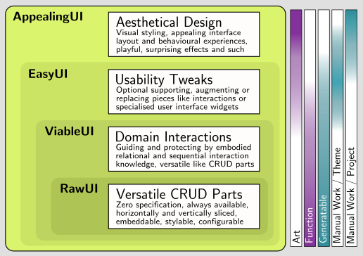
The parts shall symbolize not simply four monolithic components, like black boxes to be placed next to each other, not to mention layers. The boxes are about functionality, capabilities and styling: a ViableUI will contain RawUI features, and it is hard to imagine an EasyUI that does not comprise both.
To integrate these ingredients on an architectural level, we use an aproach that goes beyond coarse boxes as well as beyond throwing code together: fine grained pieces, combined with corresponding blueprints, that systematically and dynamically assemble themselves automatically.
A large amount of pieces and blueprints can be generated from a suitable model, or being manually crafted as universal parts. Thereby, the interplay between generated, universal and individual parts is significiantly smoother and sustainable than with e.g. a scaffolding approach.
This may or may not be the only way how to cope with the architectural challenge, but it proves that it is possible to separate the concerns on a specification level and weave them together without hindering each contributors work.
Stakeholder Perspectives
Even a good architectural integration of the different UI parts does not guarantee acceptance, pointedly one might say:
Business Analysts, Domain Experts, and Frontend developers don’t love, can’t cope with, and never will accept Modelling
Besides ideological biases, there are reasonable objections, since technologies really can get in the way of efficient work. And there will always be such rightful objections: formulating issues in an abstract way to decouple issues for the sake of clarity and economics does come with a price, however small.
But the same holds true for each invention that helps organising information or activities: of course it’s easier in the short term without documentation, backups, versioning, tickets, testing, firewalls and untouchable production servers – but seriously? All of them are accepted, for good reasons.
Technology needs to evolve and sometimes it takes a long period of time before becoming mature. A positive example: consider the long, entangled history of HTML and CSS, with many refactorings and improvements around just that boundary between art and engineering. Today, a pretty fine balance has emerged, and there are many skillful frontend developers working happily on one or the other side of that boundary, or on both sides and still much appreciate the clear differentiation between concerns.
To which degree the UI consists of Art resp. Engineering? My experience is, again, something like Recursive Pareto (80/20)*: in 80% of projects, 80% UI is engineering, of the remaining 20% again 80% contain a little art that requires small manual configuration, etc. Yes, usually there is an area where no model can ever help, and yes, there are projects where this area is really large, but in the majority of projects that area is pleasantly small.
What about the ambitioned frontend artist? Isn’t that the same old code generation wine in new skins? Far from that: the preproduced artefacts consist of a solid selection of UI components, being hold together by an assembly service, which is based on style sheets and other contextual influencing sources. A frontend designer is free to exchange whatever pieces seem suitable, and to use this assembly service deliberately. This opens up a smooth range of possibilities from a completely handcrafted solution up to a completely generated one, whereby the effort/result ratio is guided by this Recursive Pareto principle.
System Provisioning – From Business to IT
Development artefacts and activities in the context of modelling have different meanings to different people. Many, if not most non-modelling people still tend to share an understanding of modelling terms that was shaped in the ’90ies and early ’00es, along the evolvements outlined in the first post. Worse: this understanding is sunken so deep into the popular belief that it blocks the view onto further progress.
Modelling technology evolved, in small, loosely connected communities. Correspondingly the meaning of terms shifted and splitted up: at present, there is no common language to speak about contemporary modelling technology. Obviously, this is a source of misunderstandings. Therefore, in the following, I’d like to present our view that we developed along the evolution of EM/OS.
Modelling, as discussed here, is about the workflow from the business perspective onto some system up to the deployed system in operation. The diagram below illustrates the jobs and artefacts involved in that flow.
The horizontal axis covers that space between the Business and the IT realm, partionable along the information concerns shown at the bottom of the diagram as the axis’ scale. The jobs shown in the diagram are horizontally placed to reflect the information concerns that are processed by them, they are colored in lighter shades of red, yellow, and green; likewise the artefacts are horizontally stretched to cover the respective information concerns they contain, presented in darker shades of red, yellow and green.
Along the vertical axis the different approaches and artefacts are arranged according to their modernity – or here, as it is, post^n-modernity (n ∊ [0, 1, 2]) – red: signifies mechanical factory modernity, yellow: drifting agile post-modernity, and green: balanced, sustainable post-post-modernity. The chosen color in the red-yellow-green spectrum gives a coarse hint of the author’s opinion of desirability of the respective approaches.
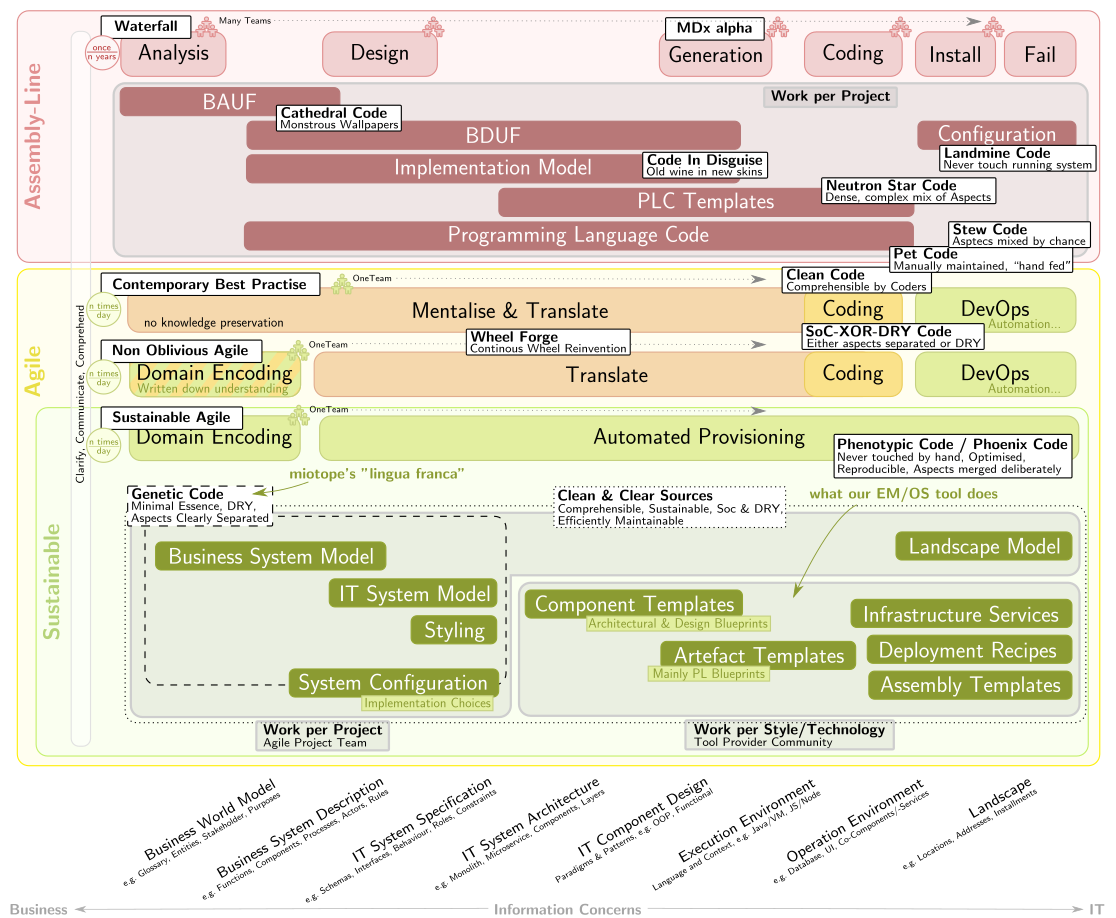
The diagram shall serve as a reference glossary, the terms are described briefly below.
- Assembly Line: the pre-agile production paradigma, characterised by: an industrial-mechanical metaphor, a long throughput time of serveral months or years, several processing steps completed one after the other, different teams working on these steps, artefacts passed from step to step
- Clarify, Communicate, Comprehend (CCC): an activity that is obviously shared by all approaches covering the knowledge acquisition every following activity is based upon; it will serve as an interesting playground for machine learning
- Waterfall: the Assembly Line production process, consisting typically of the processing steps Analysis, Design, Coding, Installation, and Operation
- MDx alpha: early attempts of partially automising the Coding step in the Assembly Line
- Analysis (Waterfall): creating a documented and optionally formalised description of the knowledge gathered in the CCC step
- Design (Waterfall): based on the Analysis, creating a documented and optionally formalised description of the target system, on varying levels of detail
- Generation (Waterfall): creating, based on the Design output, which in this case is an Implementation Model, parts or all of the target system Programming Language Code
- Coding (Waterfall): manually creating, based on the Design output, the target system Programming Language Code
- Installation (Waterfall): based on the target system code, manually transfering, packaging, distributing, configuring and maintaing the production system
- Fail (Waterfall): discovering that the initial year-old ideas are outdated, wrong and the produced system is neither completed nor desired anymore
- BAUF: a cathedral style analysis model, typically resulting from a Waterfall Analysis activity
- BDUF: a cathedral style design model describing an IT system conforming to the requirements stated by the BAUF, typically resulting from a Waterfall Design activity
- Cathedral Code: a huge, often formalised and declaredly complete model, created upfront and trying to foresee the future
- Implementation Model: a strictly formalised BDUF, intended to be used as input for an MDx alpha Generation step to produce a complete or parts of a target IT system, being out of sheer necessity Code In Disguise
- Code In Disguise: some modelling artefact, representing the usually graphical equivalent of Programming Language Code, intented to be more business oriented but de facto only slightly increasing the level of abstraction by somewhat excluding Execution Environment details, but containing most other Information Concerns
- Programming Language Code (PLC): typically manually created, classical source code within which IT systems are described, ranging from traditional 3GLs like C++ and Java up to the modern variety of scripted, functional, reactive and some declarative languages
- Pet Code: code, that in analogy to the DevOps concept of Pet Servers is manually maintained, nurtured and petted and like a beloved animal is unique
- Spaghetti Code: code, that is unstructured and mixes up information concerns to a degree so that fellow programmers are unable to modify it without high efforts and high risk of introducing errors (high overall complexity)
- Clean Code: code, that is crafted in a way so that it is easily comprehensible and modifiable by common developers and therefore well suited for mainstream manual programming
- Stew Code: (tasty) Programming Language Code, that as Clean Code is maintainable, but still by nature mixes up several different information concerns of the Business-IT-axis
- SoC-XOR-DRY-Code: Programming Language Code, that strives to be SoC as well as DRY with respect to all relevant concerns, but must fail since these couplings are not resolvable within the conceptual frame of contemporary programming languages
- PLC Templates: MDx alpha templates used to produce the target system Programming Language Code from an Implementation Model
- Neutron Star Code: a property shown by MDx alpha PLC templates, an utterly high density of complexity in unmaintainable code, resulting from the attempt to hide all complexity of the information transformation in few, ad-hoc structured templates
- Configuration (Waterfall): final manual setup of produced software on a production system, as a Pet Server, in Landmine Code style
- Landmine Code: code (here: configurations), that cannot be changed without the risk of disturbing (here: production) system operations in catastrophic ways; effectively such systems end in a state of unchangeability
- Agile: used here in a narrower sense as a classification of production workflows and information processing approaches as are found in Contemporary Best Practise or Sustainable Agile setups, characterised by direct frictionless communication, few non-automated processing steps, avoidance of hard-to-achieve or hard-to-maintain artefacts (foremost wasted documentation and models), and the strive for a high automation degree
- Contemporary Best Practise: contemporary agile approaches like Scrum or Kanban
- Mentalise: creating a mental model of the consolidated requirements spectrum encountered over time in form of small snippets like user stories, kanban cards or tickets, and creating a mental model of the consolidated IT system architecture and implementation specifics accquired from contact with code and communication with peers, effectively distinguishing the experienced team member from the novice
- Translate: the activity of creating mental ideas about the shape of desired Clean Code derived from small requirements snippets, and conforming to the knowledge gained from repeated Memorise phases.
- Coding (Agile): the activity of ideally creating Clean Code based on the results of a prior Translate effort
- Wheel Forge: manual software production, which by chance, necessity or deliberately as a side effect of elsewhere made local optimisations (re-)produces redundant artefacts to varying, not unlikely wasteful, degrees
- DevOps: (here) the activity of transporting produced software into production in a cooperative, agile, reliable and increasingly well-automated way
- Non Oblivious Agile: a Contemporary Best Practise approach that additionally cultivates Domain Encoding to reduce the risks associated with mental models solely made up in a Memorise activity, yet needs to carefully face the risk of incidentally reincarnating BAUFs or BDUFs
- Sustainable: a way of producing software that balances processed information, created artefacts and the efforts needed to produce them to minimise overall waste and thereby maximise the benefits drawable from the various elements, guided by principles like reduction of risk- and damage-propagation (multi-faceted resilience), reproducability from essential information, adaptability by recombining information pieces, experimentation by exchangeability of small components; principles that could be perceived as resembling properties of living systems
- Sustainable Agile: an Agile production method conforming to Sustainable principles; here implemented by an extended Automated Provisioning activity that relies on Clean & Clear Sources
- Domain Encoding: the activity of storing accumulated domain knowledge and target system specifications in an explicit, maintainable and non-wasteful, thereby consequently semi-formal or formal, form
- Automated Provisioning: based on artefacts created in a Domain Encoding activity, transforming the contained information into production-ready code by resorting to technological, architectural and system contextual knowledge encoded in blueprints, templates and stylesheets, and interacting with DevOps automation facilities to ideally perform automated end-to-end software provisioning
- Genetic Code: presumably model-like code that contains the minimal essential information to describe the desired (essential…) properties of a target system, consequentially DRY, not necessarily SoC, but for the sake of maintainability we (here) require the Genetic Code artefacts to be Clean & Clear Sources as well
- Phenotypic Code: complete production-ready code, that conforms to and is self-suggestingly automatically derived from some given Genetic Code, and in contrast to the latter additionally incorporates environmental constraints and properties (architectural, technological, system-contextual)
- Phoenix Code: code, that in analogy to the DevOps notion of Phoenix Servers, can be reproduced easily at any time from more condensed sources (Genetic Code), and thereby never is manually modified
- Clean & Clear Sources: sources, that as being Clean Code are comprehensible and maintainable, and in addition in a holistically balanced way are DRY and SoC, thereby overall efficiently maintainable, and in there entirety constituting a Sustainable production system
- Business System Model: a Genetic Code model describing minimally the relevant Business System Context of a target IT system, but may cover a larger area to serve further purposes
- IT System Model: a Genetic Code model specifying a target IT system
- Styling: styling of a target IT system, as a Clean & Clear Source referring to system specifics as described in the IT System Model maximally in a SoC-1 fashion
- System Configuration: selection of a broad variety of implementation choices, attached to elements of a respective Business System Model and a IT System Model
- Component Templates: a reasonable variety of blueprints describing architectural assemblies and implementation design patterns, parametrised by information from a Business System Model and a IT System Model, including System Configuration properties each, but being independent of any such specific system, and each defining a set of required artefacts to implement the respective components by selecting various Artefact Templates along with associated actual parameter values
- Artefact Templates: a large variety of blueprints describing specific IT system artefacts, in principle parametrised by all information that Component Templates rely on, plus additionally augmented parameters provided by the latter themselves; while being Clean & Clear Sources and thereby differing from MDx alpha templates, these correspond closest to MDx alpha code generation approaches
- Landscape Model: description of the spatial structure of the Business and IT operation and infrastructure systems, linking of the Business System Model and the IT System Model components to specific artefacts placed in this spatial structure and localising the whole construct by binding its elements to further virtual or specific physical locations
- Infrastructure Services: supporting software systems that provide general technical or basic domain level functionality to the target IT system, like security services, databases or user interface renderers which e.g. bind generic IT system functionality to specific media frontends
- Deployment Recipes: parametrised instructions that automatically perform deployment activities of the target IT system into various environments, being invoked in the last step of the Automated Provisioning activity and relying on DevOps provisioning technology
- Assembly Templates: parametrised blueprints that describe the assembly of a plentiful of artefacts into a running target IT system instance, used and being just in time compiled on demand at startup time or runtime; possibly by themselves created as the result of Artefact Templates
- Information Concerns: the different kinds of information that have specifying impact on a target IT system, organised along an axis ranging from the contextual Business Domain up to the technological and operational IT envrionment, separated according to a focus of respective stakeholders that are concerned with the respective information
- Business World Model: a conceptual, mental or formal model of the broader context within which the Business System exists, which furtheron contains the target IT system
- Business System Description: a description of the Business System that shall be supported by a target IT system
- IT System Specification: specification of the target IT system as a system component of the Business System, thereby comprising any desired functionality and constraints, but not containing inner architectural or technological details
- IT System Architecture: the inner system structure of the target IT system, defining the required components
- IT Component Design: detailed implementation description of the components of the IT system
- Execution Environment: description of the enclosing technical platform within which the artefacts of the produced software will operate
- Operation Environment: description of the broader IT system environment with which the instantiated target IT system will interact
- Landscape: the broad environment within which the IT system exists, containing possibly many locations and artefacts not necessarily related to this system at all
- Work per Project: work, that has to be performed within each specific project to provide a desired target IT system
- Work per Style/Technology: work, that has to be performed only once per desired style or per desired implementation technology
Remarks
Given these terms, the intention of the previous post can be stated clearer: the claim is not that something like SoC-AND-DRY-Code exists, neither that SoC-XOR-DRY-Code would suffice. Instead, the goal was to motivate that there is an inherent dilemma in the XOR, which is not solvable with contemporary PCLs and therefore needs MDx to the rescue.
Moreover, I’d like to emphasise that the PLC level is simply not the same as the Domain Encoding level, and that discussions around the pros and cons of object orientation and design principles will be fruitless if this distinction is not made.
Share Your Parsley
In this final section, I’d like to introduce a little story that illustrates how to specify an IT system with these conceptions in mind. For the sake of brevity, I focus on UI concerns for horizontal slicing, and on microservices for vertical slicing.
Old Joe always had a couple of herb plants in his backyard. If you ran out of parsley on a Sunday, Old Joe was the one to go for. In exchange for his help he often received small matching gifts, like the secret of some recipe, or the offer to get something back when Joe is in need. That way, Joe gathered much knowledge about plants in general and the ones in his neighbours’ gardens in particular.
Over the years, it became the habit of his friends to call on Old Joe for a herb or a little chat, and to keep track of his herb empire Old Joe maintained a list of the herbs in town:
Herbs in Town - Harry: chive, 1 plant
- Martha: sage, 1 big plant
- Edith: parsley, 2 plants
- Myself: lovage, 1 plant; oregano, 2 plants
|
When Young Mary was really young, she liked to play delivery service: fetched the herbs from Old Joe and rode them by bike to the cook in distress, usually earning a tiny reward.
In the progressive local school Young Mary took courses in Design Thinking, Lean Business and Agile Software Development. Well prepared for life, she and Joe founded their first startup: Share Your Parsley. Since Joe and Mary live in the Digital Age, are open to learning and curious to play with new technologies, they just skipped spreadsheets and betted on Model-Driven Technology, as offered by their local IT shop.
That is how their Herb Manager V1.0 came to live, which handles Old Joe’s list as well as customers and herb requests. Here’s the implementation in markdown notation:
Herb Manager V1.0* Herb CoreClass ** Name String ** Sources Source(*) * Source CoreClass ** Amount Number ** Neighbour Neighbour(1) * Neighbour CoreClass ** Name String * Request CoreClass ** Herb Herb(1) ** Amount Number ** HerbFrom Neighbour(1) ** HerbTo Neighbour(1) |
This is the IT System Description of that piece of software. You may also want to have a look on Mary & Joe on oomodels (inspect the source code there to validate that it matches the snippet above). A RawUI is easily constructed from that spec. For starters, everything else that makes up a CRUD/RawUI app can be left in the default state.
A little later Tom’s sister, old Jane joins the business to help to enter herb search and delivery requests. Since Old Jane is not used to nerdy user interfaces (and never will be), Mary & Joe agree that it’s time for a ViableUI. Together with Jane, they design a little interaction flow:
Herb Manager V2.0
|

This ViableUI is still part of the IT System Model, maintained by Mary & Joe themselves (Mary is clever). Yet they switched to a diagram representation, since interaction flows are ugly by nature in text form (your mileage may vary). The diagram shows the Herb Manager model in graphical form, and the interaction flow for easier data entry (eyes denote visible data, pencils denote editable data). Note the RequestEntry thing: it couples the interaction flow to the backstage, it keeps the handled data together and provides hooks to do the actual assembly.
The business flourished and soon there are so many customers that a self-service herb site becomes unavoidable: a browser-based public portal to place herb requests.
Our herbal manager is already capable of handling this, but we need to make it more restricted to face the wild, wild web. That would be:
Herb Manager V3.0* Herb CoreClass * Source CoreClass * Neighbour CoreClass,UserOwned * Request CoreClass |
The new annotations are printed in red. The model is shown in text form to simultaneously display these new properties.
This is still part of the IT System Model, but here Mary & Joe got help from their local IT shop. How so? By collaborating on the IT System Model via the integrated ticket system. Note, that this model still satisfies the criteria for Genetic Code.
Not all neighbours know herbs by their names, usually, they just point at them. The solution is clear: an EasyUI that allows for clicking at herbs in an image of a little garden (just placing images next to each herb would be too simple for our example 😉 ).
Rendering StyleSheetADO-Request ADOF-Herb { |
This snippet is part of the application Styling, belonging to the IT System Specification. It refers to a ClickableImageSelector, which may or may not exist for a specific user interface renderer. If it does, it would be part of the Infrastructure Services, still generic, and can be considered a Clean & Clear Source.
The business grows and attracts more and more people in the nearby metropole. Now Mary & Joe face a problem: the urban folk wants the latest fancy mobile UI, while the neighbours in the village still use older browsers, and will for a while.
What to do? Give up the initial tiny, but very loyal user base? That’d be never an option for Old Joe. Besides – it’s not necessary. From the very beginning, there’s been an IT System Architecture specification in use, a small piece of System Configuration, which controls the selection of Component and Artefact Templates to apply. It looks like this:
 |
The diagram says that our system consists of a socalled Fullstack Application, which lists all the required Infrastructure Services to include, and which is augmented by a tailor-made HerbManager Core, which provides the HerbManagers specific functionality and styling.
For the moment, we’re interested in the selected infrastructure services:
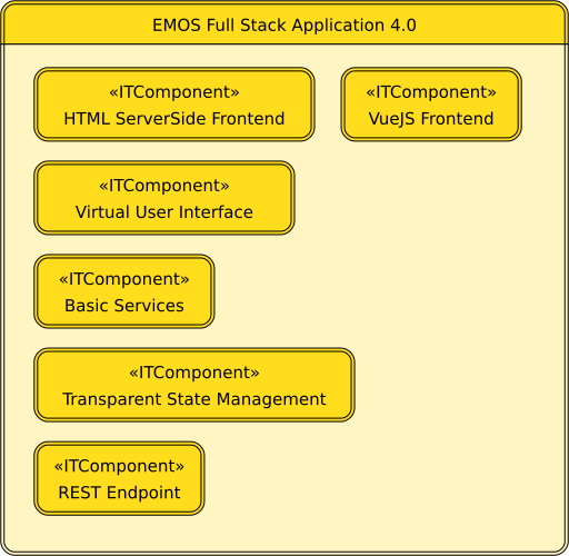 |
The default application architecture contains only the HTML frontend. In our simple example, it suffices to add the VueJS frontend, as shown in the diagram above. This works, since in that case we really only want to add an additional, ready-made renderer. Note that this only can work here because our UI specification is not specific to these frontends.
For completeness, here’s the architecture description of our HerbManager Core (full stack component), the diagram describes which components to produce from our model:
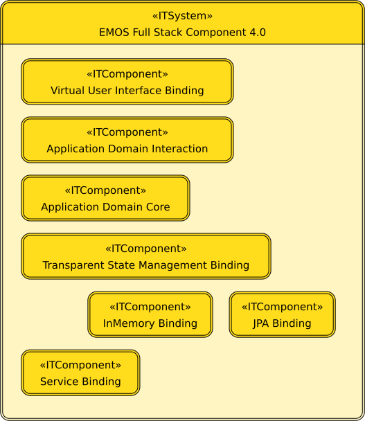 |
Yet even our EasyUI will not meet the expectations of a mobile user, clearly we need an ApealingUI with a herb pluck touch gesture.
Say we implemented this gesture in a VueJS-component named VFEPluckableHerbSelector, overriding the default selector “VFESelectorFromMany”, which would present a standard choice-box. To make this functionality available we configure it in the frontend rendering stylesheet:
Rendering StyleSheetADO-Request ADOF-Herb { |
The modifications consist of a custom-made frontend component located in the Infrastructure Services, plus a style sheet entry in Styling. This modification is outside the scope of Mary & Joe core competencies, but still the binding in the style sheet is understandable, and the overall amont of code fairly appropriate.
What if a modification affects not a single UI item, like a selector, but the replacement of a complex UI part, say, rearranging a dialog? Then we just redefine this UI part, by providing a new component and registering this component. This is possible, since the aggregation of UI parts is also defined as components, which then recursively include their subparts.
Won’t the whole approach become too brittle in the long run? Won’t complexity eat us up, finally? Well, that was all but clear to us from the outset, in the early years when we started with EM/OS. But from today’s perspective, after some lengthy years of maturing, I dare say that this pit has indeed a bottom – deeper than expected, but a bottom.
Back to Mary & Joe: meanwhile, Mary’s brother Tom joined the business and manages the delivery department. As siblings, Mary and Tom sometimes cannot easily agree on details, so they think it’s best to create a spin-off, managed by Tom alone. Yet, of course, both share the same technology spirit, so they decide to go for Microservices, of course sharing the core specifications!
For simplicity, let’s say Tom’s model imports Marys’, without any fancy filtering, picking, common base models and such. Tom’s model might look something like this:
Toms Delivery Manager* Delivery CoreClass ** Request Request(1) ** Boolean Delivered |
The system now consists of two microservices, each of which implements a partially similar, but somewhat different model. To describe this, let’s look again on our IT System Architecture description, which includes one generated component, our HerbManager Core, which was based on our sole model.
We want to split this core component into two separate parts, which can be produced and deployed independently. We do this by modifying the specification accordingly, as shown here:
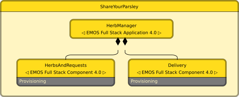 |
Now, instead of a sole generated component, we have two of these. How do we relate them to our two models?
You may have noted the dark grey Provisioning boxes at the bottom. They say that for these component there are corresponding provisioning subsystems, as part of their infrastructure. We can zoom into them:
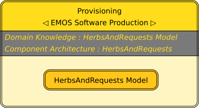 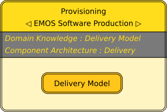 |
We can see that these provisioning subsystems are a kind of predefined, parametrised EMOS Software Production systems. Furtheron, they contain model resources: a HerbsAndRequests Model and a Delivery Model. This is how our models are linked to the two microservices.
To complete this example, here is the diagram that specifies the parametrised EMOS Software Production system. It’s purpose is to declare the existence of such a system with the given name, and to declare it’s parameters.
 |
Behind all those diagrams from above is still the mechanism of attaching stereotypes and properties, as described in the earlier miotope post. E.g., to say that we want to deploy our microservices as docker images into the cloud, we add these properties (again in text notation, for readability):
Docker Deployment* ShareYourParsley ITComponent
...
* HerbsAndRequests Microservice
+ XMDistribution.Packages=["DockerImage"]
* Delivery Microservice
+ XMDistribution.Packages=["DockerImage"]
...
|
A possible description of the deployment location would look like this, fitting well into a Landscape Model,:
IT Landscape* TomsTown ITLandscape
* ShareYourParsleyPortal ITSpace
+ XMSpace.Location="oorl://....cloud-provider-locator...."
* ShareYourParsley ITComponent
...
|
Conclusion
The purpose of this post was to show more precisely how the ideas from the first part of the walkthrough might be implemented, and thereby demonstrate how it might be possible to describe IT Systems that satisfy the quality criteria introduced in the previous post on Model Tagging.
The gathered conceptual material shall be used to prepare the ground for a refactored language capable of growing a modelling biotope. Growing requires scalability, from tiny pieces up to complete systems, over time. The intended quality shall help to ensure this.
Previous post concerning miotope: Concerning Concerns – An Architectural Walkthrough of the Business and Information Systems Arena
Next post concerning miotope: Concerning Concerns – An Architectural Walkthrough (2)
I’m working in IT since the late ’80ies of the last century. Half of my time I spent crafting software of various kinds for customers, increasingly based on model related technology. The other half I invested in research and development of a fully model driven software production system and respective suitable concepts, most of which is available as open source or creative commons. Since the beginning of the millenium I’m doing this in my own Hamburg-based company and offering software production as a (model based) service — Andreas

Recent Comments