BPMN models focus their efforts on representing how industrial processes work. This leads to build an abstract model that only tackles with the behavior of the company. How BPMN models are actually implemented in real code is not described in the own business process model, this depends on the decisions of the developers based on their own opinion or additional (partial) information available in other system models.
Therefore, taking as input the same BPMN model, the generated code is usually different depending on the developer that interprets the model and implements the code. Indeed, even though the primitives of the BPMN model are unequivocal for the functionality of the system, how this functionality is displayed in the user interfaces is not tackled in the models.
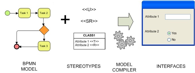
We want to reverse this situation and make sure that two different developers end up generating the same interfaces when starting from the same BPMN models. In order to avoid the subjectivity in the process to transform BPMN models to interfaces and to automate the process as much as possible, we propose:
- An extension of BPMN models with UML stereotypes to enable designers to be more explicit on the GUI to be derived from the models
- An automatic code generation process from the BPMN models to GUIs, following the MDD paradigm.
Identification of transformation rules
In order to better understand the information to be added to the BPMN models and identify the required transformations from them to the UI code, we have analyzed 7 Bizagi projects. Bizagi is a suite tool to work with BPMN models that includes real projects (with the BPMN models and the interfaces).
We have used 7 of these projects to generalize possible transformation rules from BPMN to user interfaces. In order to systematize the process of defining rules, we have used BPMN patterns. More specifically, we have:
- Identified the different patterns in the models.
- Analyzed the type of interfaces and widgets that generate each pattern.
- Elaborated a set of widget alternatives for each transformation rule depending on developers’ preferences.
We have focused our analysis on the three most frequently used BPMN patterns:
- Sequence pattern: this pattern appears when you have to finish a task before you can continue with the next one sequentially.
- Exclusive decision pattern: this pattern appears when you must choose a single path among several ones that are available depending on a decision or process data.
- Synchronization pattern: this pattern appears when two or more branches of the process are merged into one. It is expected that all incoming branches are completed before continuing the next task.
Note that the interface generation depends not only on the behavior expressed in the BPMN models but also in the data of the system. For example, for the generation of a form to provide data to the system we need to know the structure of the data that is behind the form. In order to solve this problem, our stereotypes do not work only with visual features but also with structural ones. That is the reason why we have included UML Class Diagrams together with BPMN models as input for the proposed rules.
Next, we list the set of rules identified through the analysis of the three patterns in the 7 Bizagi projects:
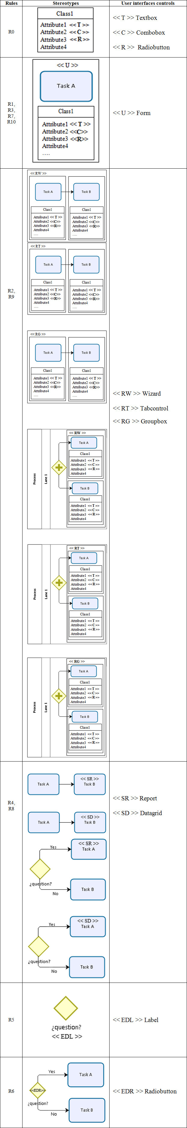
- R0: A lane usually represents a form.
- R1: The input fields of the form are extracted from the attributes of the classes, each attribute generates an input field. Alternatives: (1) input fields that accept any type of textual string (Textbox); (2) input fields that are a closed list where the user must select one element (Combobox or Listbox), (3) input fields that represent a Boolean value (Radiobutton or Checkbox).
- R2: If user type tasks are in the same lane and there is a dependency among them, this lane generates interfaces to guide the user through a process of several steps. Alternatives: (1) Wizard: the navigation throughout the different forms is forced to be done in a specific order. The number of forms depends on the number of user type tasks and each form is a user type task in sequential order; (2) TabControl: a form with multiple tabs such a way each user type task generates a tab; (3) Groupbox: the number of groupbox depends on the number of user type tasks. Groupbox can be generated such a way each user type task in sequential order generates a groupbox.
- R3: If user type tasks are in different lanes and there is a dependency among them, each lane generates a form.
- R4: If task A is user type and task B is service type and there is a dependency between them, then task A leads to generate a form. Alternatives: (1) report: designer of reports and graphics; (2) data grid: it is a control that displays data in a customizable grid.
- R5: The text that appears in the exclusive decision gateway usually represents a Label that includes a question such a way the user can take a decision.
- R6: The text that appears in the connection objects of the exclusive decision gateway, generates a radiobutton. Each option of the Radiobutton is a text of each connecting object of the gateway.
- R7: If the task that continues in the exclusive decision gateway is of user type, it generates a form.
- R8: If a service type task A continues after the exclusive decision gateway, the previously registered data is processed in task A by a web service or a scheduled event. This rule uses the same alternatives as Rule 4.
- R9: If after the synchronization gateway there are user type tasks that are in the same lane and there is a dependency among them, interfaces to guide the user through a process of several steps are generated. The alternatives to represent the different steps are exactly the same as the alternatives explained in Rule 2.
- R10: If after the synchronization gateway the user tasks are in different lanes, each lane generates a form.
Enhancing the BPMN models through stereotypes
Once we have the set of rules, we need a specific syntax in the BPMN models to know when each rule must be applied and what alternative (if any) is preferred for each widget in the interface.
In order to solve this problem, we propose an extension of BPMN with stereotypes. We have used the visual notation of BPMN and UML Class Diagram and we have included labels to express the alternative to apply to each rule. Taking as input the BPMN model enhanced with the stereotypes, a model compiler can interpret such models to generate the interfaces automatically. Next figure shows the stereotypes that are proposed for each alternative of the rules.
A BPMN to GUI example
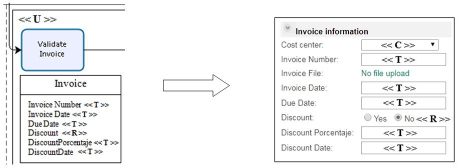
Next figure shows an illustrative example of an enhanced BPMN model and the generated interface. The stereotype <<U>> is used to indicate that the task is “user type”, so according to our rules (R3), this should generate a form. Related with the task, there is a class in a UML Class Diagram. The stereotypes of its attributes define the types of widgets. Attributes with any possible value have the stereotype <<T>> to generate a generic TextField while attributes with a closed list of possible values have the stereotype <<R>> to generate a RadioButton (R1).
Final remarks
Our approach does not cover the full generation of code, only interfaces with no functionality. Moreover, we have defined a set of rules using the most frequently used patterns in BPMN. So, we cannot apply our proposed rules to parts of a BPMN model beyond the use of these patterns.
As future work, we plan to process more patterns and extend the study to other real projects beyond the Bizagi repository. We also have in mind to study what alternatives are the best ones in each context with the aim of improving the usability of the generated interfaces.
More details of this work can be seen at: https://ieeexplore.ieee.org/document/8406675/


Recent Comments