In UML, sequence diagrams (SD) describe a type of interaction that focuses on the partial order of message interchanges between objects. SDs support modularity mechanisms and combination operators, such as parallel, alternative, optional, or repeated action or event occurrences (par, alt, opt, loop) in the definition of the interactions. The semantics of UML SDs are defined in terms of valid and invalid traces. Each SD defines a set of possible sequences of interactions between the objects of the system, called traces. A valid Sequence Diagram is an SD whose set of traces is allowed by the system specification and does not violate its constraints.
Most UML tools support the specification of SDs. A few of those tools also provide analysis capabilities such as checking whether the trace of a program or model execution is valid, producing test cases, or even generating code from them. However, all this potential of SD is not fully exploited by most modeling tools, which only enable their representation. Furthermore, despite their apparent simplicity, SD can hide very complex behaviors and their specifications are in general difficult to understand.
In our case, we are interested in one modeling tool, namely USE (UML-based Specification Environment), which is one of the most popular textual UML modeling tools. USE provides full OCL support and enables a full range of analysis capabilities. It is successfully used in lectures at different universities and also as a supporting tool for research.
USE provides a textual OCL-like action language called SOIL for specifying the behaviour of operations, together with an engine able to execute them. This feature enables the execution of scripts as a sequence of operations invoked by an external actor. However, USE does not allow to specify sequence diagrams that describe in general the valid execution traces of the system. In USE, they are automatically produced from the execution traces of scripts, allowing modelers to visualize the interactions which occurred between the objects in the system. This means that SDs are projections of executions and not general specifications of the possible interactions.
For this reason, we decided to investigate how to provide USE with capabilities for the general specification of SD, together with the automated generation of all the valid traces that comprise the semantics of such specifications in terms of SOIL scripts. This way, software engineers could specify SDs in USE, and automatically have access to all behaviours that comply with these specifications. The tool that we developed is an extension of USE that enables this general specification.
Our Proposal
Given the textual character of USE, the natural manner to specify SDs is using a textual language, too. This is why we decided to use the ITU-T Message Sequence Chart (MSC) as the textual grammar for the specification of SD in USE. MSC is an international standard notation, UML SDs are based on MSC, and its rules are a subset of the latter.
To start with, we selected a subset of MSC to describe the most simple interactions and four combination operators: par, alt, opt, and loop. For this purpose, a grammar was defined using Xtext in order to parse the information in the MSC files and generate the corresponding SOIL scripts.
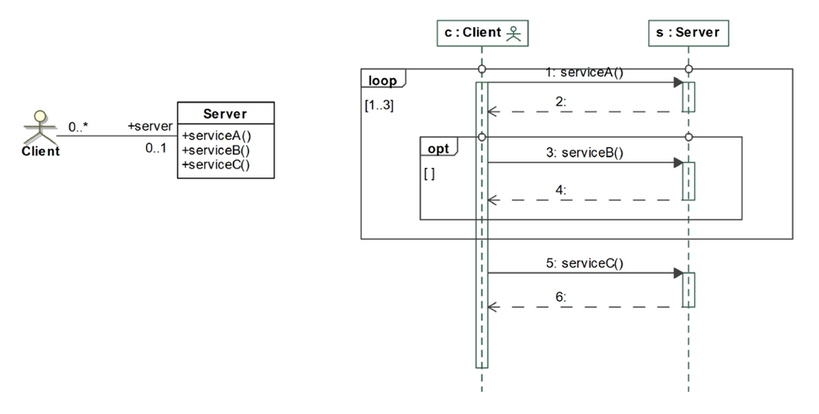
To illustrate this, the following figure shows a simple client-server system specified by means of a class and sequence diagrams. The class diagram describes the objects and the operations they provide, while the UML sequence diagram shows the possible interactions.
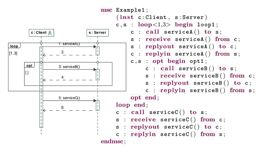
The corresponding textual specification of the SD of this system described using MSC grammar is the following:
msc Example1

(inst c:Client, s:Server)

c, s : loop<1,3> begin loop1;

c : call serviceA() to s;

s : receive serviceA() from c;

s : replyout serviceA() to c;

c : replyin serviceA() from s;

c, s : opt begin opt1;

c : call serviceB() to s ;

s : receive serviceB() from c;

s : replyout serviceB() to c;

c : replyin serviceB() from s;

opt end;

loop end;

c : call serviceC() to s;

s : receive serviceC() from c;

s : replyout serviceC() to c;

c : replyin serviceC() from s;

end msc;
Our goal is to be able to specify the structure of the system with USE, and the valid interactions with the textual MSC specification. Our tool parses these specifications and automatically generates the SOIL scripts that generate all the valid executions according to the SD. Although, in theory, this should be a simple problem, in practice we had to address some subtle issues. We summarize below these issues and how we built our tool to solve them. Interested readers can consult the full paper, which was presented at the OCL Workshop, held with the MODELS 2019 conference in Munich, in September 2019.
Generalization and behavioural script generation
The first limitation that we had to address is the fact that USE does not allow the general specification of SD. It only allows specifying SD as projections of particular executions. To overcome this issue, our tool generates every particular execution given a specific SD.
For example, six executions are possible from the client-server system SD that we showed before, and hence our tool needs to generate six SOIL scripts so that the user can test every possible scenario defined in the SD and check the model constraints on it.
By script we mean a sequence of commands or instructions that specify a particular behavior. For example, the client c invokes serviceA() on server s, waits until s replies, and then c invokes serviceB() on s and waits for its reply.
The Choreographer
General SD specifications allow any object to invoke other objects’ services in any order, and with no need to interact with third parties or with any external object. However, USE employs an external actor to drive the system behaviour, modeling the user that invokes the system objects’ operations from the USE console.
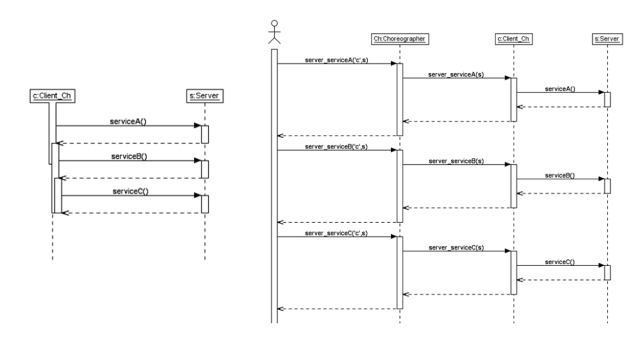
To overcome this limitation, we introduced an additional object called the Choreographer. This object is the one in charge of calling the methods which have no trigger defined in the MSC. The USE external actor will call the methods generated in the Choreographer by our tool, and it will be the one to trigger the generated methods in the corresponding objects. All this is handled transparently by our tool. One of the SD corresponding to the client-server system described above, as generated by our tool, is shown in the following figure. The left side shows the interactions between the system objects, hiding the USE actor and the Choreographer’s lifelines. The right side shows the same SD, but without hiding these two lifelines.
A prototypical implementation
Our tool is available as an Eclipse plugin, which can be downloaded from our Github repository, together with the specifications of several systems and applications that we have developed to evaluate and validate our proposal.
To validate our proposal, we specified different systems and applications, whose specifications and associated artifacts are available here. For example, the following system represents a publish-subscribe notification system able to notify all subscribed users about two types of events, A and B, coming from an event producer. The UML specification of the system using a class and sequence diagram is shown below:
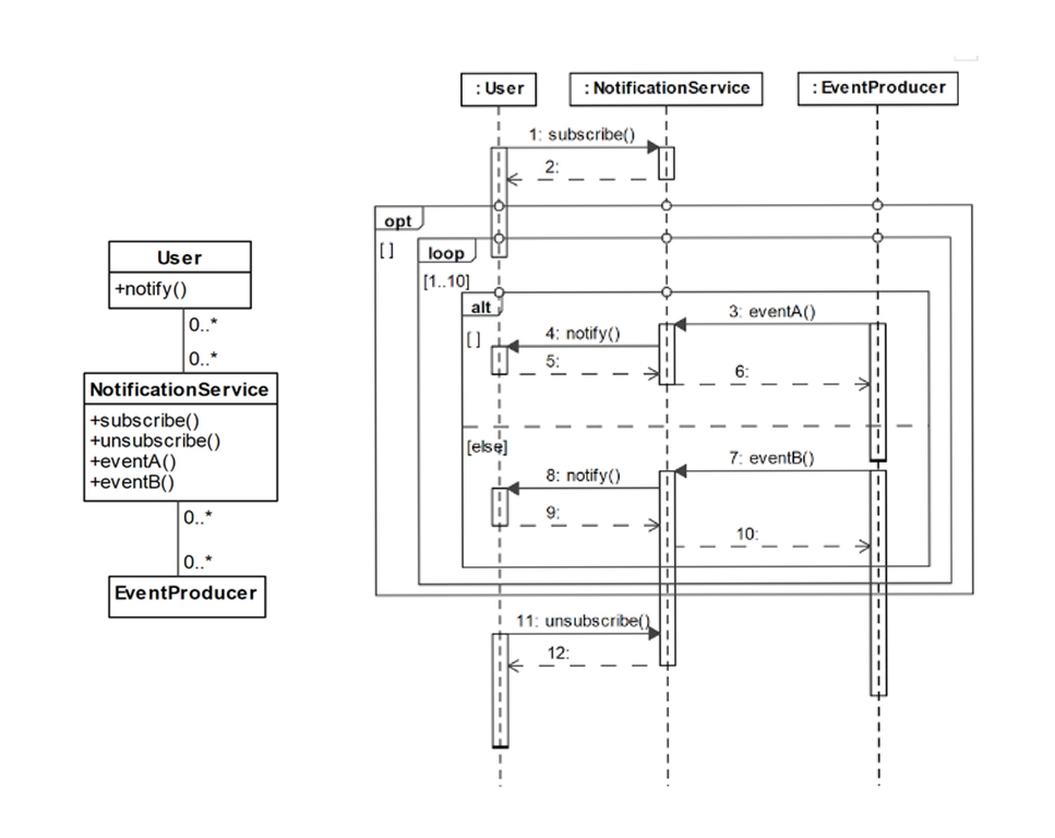
The corresponding textual specification of the SD of this system is as follows:
msc Example5

(inst user:User, ns:NotificationService, provider:Provider)

user: call subscribe() to ns;

ns: receive subscribe() from user;

ns: replyout subscribe() to user;

user: replyin subscribe() from ns;

ns, provider, user: opt begin opt1;

user, ns, provider: loop<1,10> begin loop1;

user, ns, provider: alt begin alt1;

provider: call eventA() to ns;

ns: receive eventA() from provider;

ns: replyout eventA() to provider;

provider: replyin eventA() from ns;

ns: call write() to user;

user: receive write() from ns;

user: replyout write() to ns;

ns: replyin write() from user;

alt;

provider: call eventB() to ns;

ns: receive eventB() from provider;

ns: replyout eventB() to provider;

provider: replyin eventB() from ns;

ns: call write() to user;

user: receive write() from ns;

user: replyout write() to ns;

ns: replyin write() from user;

alt end;

loop end;

opt end;

user: call unsubscribe() to ns;

ns: receive unsubscribe() from user;

ns: replyout unsubscribe() to user;

user: replyin unsubscribe() from ns;

endmsc;
Interestingly, even for such a simple system, the number of generated SOIL scripts, which corresponds to the set of valid traces in the sequence diagram, is 2047! This is why automated tool support for the analysis of SD specifications is so important.
Conclusions
Sequence diagrams are fundamental elements for the specification of the behaviour of objects, and in particular of their interactions. They describe the partial order in which messages should be exchanged between objects, and can have powerful applications such as producing test cases or generating code that verifies that the system behaves as intended.
However, the specification of sequence diagrams is not easy because they are more complex than they appear to be, and therefore they are difficult to understand and prove correct. In addition, the support provided by most UML modeling tools for the specification and analysis of SD is often limited, because it basically boils down to visual representation and syntax checking.
Our work has consisted in the extension of the USE tool with an Eclipse plugin for the textual specification of UML sequence diagrams, using the ITU-T notation of Message Sequence Charts, and the automatic generation of all valid behaviours that comprise the extensional definition of the SD, i.e., all the valid traces of the SD. People tend to underestimate the complexity of sequence diagrams, and therefore a tool like this is very helpful for understanding the behaviour of systems, and also for assisting software engineers to generate test cases to improve their designs and the systems they build. In addition, it can be useful in those courses that employ USE as a modeling tool to teach SD, complementing its current functionality, and assisting students to understand the power of Sequence Diagrams.


Recent Comments