
Guest post by Stefan Hennig on model based user interface development in the Industrial Automation domain. Enjoy!
The operative states of industrial automation facilities are monitored and operated by qualified personnel using pertinent Human Machine Interfaces (HMI). These software systems map the technical process and the automation devices, respectively, to graphical symbols and thus, they provide a simplified representation of complex instrumentations. The following figure compares a “real” plant with its simplified HMI.
 * * |
 * * |
|
Laboratory Plant |
HMI of a Laboratory Plant |
The development of such HMI for process visualization and operation is very sophisticated and thus, expensive. This situation is aggravated by the fact that those HMIs are as manifold as their field of application and the devices to run the HMI. Repetitive programming and engineering for different devices and technologies is the consequence.
Hence, a new development method is required. During my research at the Dresden University of Technology we gave the MDE approach a shot – and we succeeded! We analyzed several conventional engineering tools: These tools capture three different kinds of information: (1) Information related to the graphical user interface (GUI) to provide a schematic view of the process and interaction means for operators. (2) Information about real time process data which values affect the GUI so that it displays the current state of the process at any time. Vice versa, these values can be altered through the GUI by operator interaction. (3) Information concerning application specific logic enables the realization of very specific requirements, e.g. a specific kind of preprocessing data. Due to the diversity of industrial processes it is not worthwhile to provide standard building blocks for each foreseeable requirement.
Based on the collected requirements, we realized a Domain Specific Language (DSL) and the tool Movisa using the Eclipse Modeling Framework (EMF) in order to model an HMI for monitoring and operating industrial processes. Conventional engineering tools distinguish three kinds of information that have to be taken into account for designing the DSL. This information differ from each other fundamentally. Elements describing the GUI are structured in another way than elements describing process data. Furthermore, a modeler might feel more comfortable if she or he can arrange GUI elements graphically on the screen in a WYSIWYG manner. By contrast, it can be a burden modeling process data graphically. These circumstances demand appropriate subdomains using different concrete notations: (1) The Presentation Model specifies GUI components which are typical for industrial automation. (2) The Client Data Model captures the necessary configuration parameters so that communication can take place and process data can be accessed. (3) The Algorithm Model provides application specific logic in a technology independent manner by means of Executable UML [Mellor2002]. These models are aggregated by a superior Visualization Application Model.
Let’s have a more detailed view on the Presentation Model: It captures GUI Components for onscreen presentation which are sufficient for creating visualization solutions, thus, their configurable properties meet the requirements of industrial GUIs. For instance, the Movisa DSL provides not only standard UI controls such as Buttons or Checkboxes, but also Alarm Control widgets, Trend Chart widgets etc. The Movisa DSL contains means for aggregating these rather elementary widgets to more complex components: (1) using a Complex UI Component widgets can be grouped, e.g. to ; (2) using a Panel, a specific view on the technical process can be established. The following figure shows the relevant excerpt of the Metamodel.

Excerpt of the Movisa DSL’s Metamodel
Each UI Component of the Movisa DSL provides a set of configurable properties which were classified by the following three categories: (1) Representation for configuring the initial appearance on the screen. (2) Animation for configuring the dynamic behavior of the UI Component. (3) Interaction properties allow to configure operator’s interaction means and defining the resulting actions.
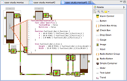
A concrete syntax – the metamodel’s face modelers interact with – of GUI models needs to represent the particular UI Components using a graphical representation since this allows modelers to think and work comfortably in this domain. Moreover, a good DSL tool should reduce development efforts: For instance, it should enable modelers to arrange UI Components on the screen while storing the corresponding properties, e.g. Position or Size, of the modeling elements in the model. Such high-fidelity concrete syntax of the Presentation Model’s elements has been provided by means of Eclipse GEF. However, it is very difficult and time-consuming to model each property of a UI component graphically or using lots of wizards and dialogs. There are, e.g. Animation properties with lots of options and cross-dependencies. As a consequence, a textual representation based on EMFText contributes to the objective of efficiency. This also allows a fine-grained adjustment of the component’s properties — in contrast to the graphical concrete syntax which fosters model’s readability and intuitive editing. Therefore, we combined a graphical and a textual concrete syntax which can be seen in the following figure.

Screenshot of the Movisa DSL Tool in action: It shows the high-fidelity concrete syntax notation of the Presentation Model fostering an efficient modeling experience. It augments graphical syntax notations with textual ones.
The basic feasibility of the DSL has been proven using a prototypical tool implementation and by means of several real-world case studies. However, a key finding in my PhD thesis was that practitioners and automation engineers, would only accept the application of the MDE approach, especially the use of DSLs, if there’s a powerful tool which hides the complexity of MDE behind a convenient and easy-to-use workbench. This is exactly what we are currently striving for.
References
[Mellor2002] Stephen J. Mellor and Marc J. Balcer: Executable UML – A Foundation for Model-Driven Architecture. Addison-Wesley, 2002.
FNR Pearl Chair. Head of the Software Engineering RDI Unit at LIST. Affiliate Professor at University of Luxembourg. More about me.

The key to increasing productivity in your operations is the intelligent linking of industrial software with industrial automation technologies, drives and services as well as industry solutions for vertical markets – all from a single source.
http://www.usa.siemens.com/industrial-productivity/industrial-productivity.html
HOw soon until a touchscreen interface replaces this (in your opinion)?
If I understand you correctly, you are afraid that the approach mentioned in the article does not support touch gestures. I can put your mind at ease: The approach does provide interaction properties with common touch gestures. Hence, it will never be replaced — on the contrary, based on an extensible architecture, it can for sure handle future interaction means.
How does this relate to the UI options present in SCADA solutions?
We analyzed widely used SCADA systems regarding their UI options, abstracted them in a common metamodel, and realized a UI widget modeling language that provides those UI options of SCADA systems. Furthermore, we implemented an extensible library approach, where you can assemble your own (complex) widgets…